Transformers are deeply critical to the reliability of an electrical power system. Faults that involve transformers are usually catastrophic events due to their physical size and available short circuit.
Power interruptions can affect large areas and require extensive downtime for repair. The cost to replace a single substation transformer is enormous, with expenses easily reaching the $1,000,000.00 mark, depending on it’s capacity.
Windings are a critical component of transformer design as the number turns of the primary and secondary winding determines the ratio of the transformer. The most common causes of transformer failure include overloading, deterioration, power surges and moisture.
Many of these failures occur within the transformer winding insulation and often times can be detected early by conducting rigorous visual, mechanical, and electrical inspections throughout its service life.
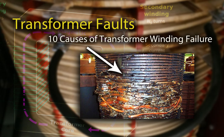
1. Turn-to-turn faults
Turn-to-turn faults are one of the most common faults in a transformer that results in catastrophic events such as explosion, and winding or core deformation. If heat inside of a transformer is not properly dissipated, the temperature of the transformer will rise continually, which may damage the insulation. Overloading a transformer will cause thermal stresses that can subject a transformer to decreased efficiency and dramatically reduced service life.
Related: Transformer Cooling Systems and Methods Explained
Dielectric stresses such as voltage spikes and harmonics can cause the insulation between turns to breakdown and eventually fail. Poor power quality can also lead to an increase in temperature and subject the transformer to thermal stresses.
Mechanical stresses caused by seismic shifts or other foundational issues can alter the spacing between insulated components or physically deform windings which can alter the turns ratio and subject the transformer to abnormal dielectric stresses.
2. Surges
Surges caused by lightning and switching can be transferred from one voltage level to another through transformer couplings, leading to turn-to-turn faults caused by dielectric stresses. Along with surge phenomena, a system can also experience a longer term overvoltage from electrical faults.
Many transformer failures happen after an incident, such as a lightning strike or a failure down line from the equipment. Surge arresters can be installed to limit overvoltage conditions by conducting the surge current to ground. After passage of the surge, the arrester returns to its initial state.
Related: Surge Arresters: Selection, Application and Testing Overview
3. Moisture
Moisture in a liquid-filled transformer can cause issues that result in irreversible damage to the paper insulation. If the transformer tank is not properly sealed, moisture will eventually work its way into the insulating fluid. It is also possible for moisture to enter a transformer during the natural breathing process if the silica gel is not well maintained.
Improper fluid sampling techniques can also lead to moisture ingress through the valve or other opening. Moisture will decrease the oil break down voltage and can lead to increased temperature rise.
Dry-type transformers are especially susceptible to moisture because they require very large ventilation ports to allow less restricted airflow through the windings. The enclosure must maintain adequate clearance and working space to properly dissipate heat.
Transformers operating indoors can be kept in controlled climate to increase efficiency and prolong service life. Splashing, flooding, and excessive humidity are the most common forms of moisture ingress.
4. External Faults
External faults are events that occur outside of the transformer, and are not necessarilly preventable by regular maintenance. Lightning strikes, down trees, animals, and other damage from the outside that cannot be prevented are external faults. It is important to have redundant equipment or a plan in place to make repairs as fast as possible in the event of an external fault.
5. Overheating
A higher temperature on a neutral termination may indicate the presence of harmonics. Per IEEE 519, the total harmonic distortion for voltage should be less than 5% for systems below 69 kV. The total demand distortion for current should also be less than 5% depending on the size of the source in relation to the load.
Excessive harmonics on the third or fifth level often point to interference from electronic loads. It is important to keep dry-type transformer enclosures clean and the area around them clear. Items placed near or against the transformer will restrict the heat transfer around the enclosure.
Related: Power Quality Analysis: Basic Theory and Applications Explained
6. Open Winding
Upon a single phasing condition, the resulting voltage and current on both the HV side and LV side greatly depends on the transformer winding connection and core construction. Single phasing condition is very difficult to detect by relays monitoring current on the LV side of the transformer. Open winding conditions often occur in rural or remote areas where the chances of broken conductors, loose connections, and blown fuses are high.
7. Deterioration
Poor electrical maintenance is the leading cause of unplanned downtime, poor energy efficiency, and premature equipment failure. Because a transformer fault is usually of very serious nature, regular visual inspections and periodic insulating testing or fluid analysis are the best assurance of continued high reliability. Transformers that are neglected or fall under a “reactive maintenance” approach will often fail well before the end of their expected service life.
8. Core Faults
Transformer cores are constructed by stacking layers of thin iron laminations, separated from its neighbors by a thin non-conducting layer of insulation. Over time, the transformer core adhesive starts to break apart and the laminated layers separate from each other slightly.
The vibration of these layers is the humming noise you can hear and once the adhesive starts to break, the sound gets louder. Faults in the core can directly affect the transformer efficiency. The breakdown of core insulation allows for an increase of eddy currents which cause excess heat that eventually effect the windings.
Related: Transformer Humming Noise Explained
9. Phase-to-Phase Faults
Phase-to-phase faults are unintended short circuits between phases. Transformers can experience this type of internal fault for several different reasons such as: overheating, contamination of oil, winding failure, and deterioration of the insulation system. Failure can also occur between HV and LV windings wrapped around a common phase.
10. Mechanical Failures
Mechanical failures are electrical faults that occur when mechanically operated device critical to a transformer or electrical circuit fail to operate. An example of a mechanical fault would be an upstream circuit breaker that fails to clear a circuit. Mechanical faults can also happen when the transformer cooling system fails to operate properly, resulting in elevated winding temperatures.