Current transformers (CTs) are essential components in the monitoring and protection of electrical power systems. These instrument transformers are specifically designed to convert high primary currents into lower secondary currents, enabling their utilization with meters, relays, control equipment, and various other instruments. By accurately transforming and scaling current measurements, CTs facilitate precise monitoring and reliable protection of power systems.
The significance of instrument transformer tests is frequently overlooked. Current transformers utilized for metering purposes need to exhibit a high degree of accuracy to guarantee precise billing, whereas those employed for protection must respond swiftly and accurately in the event of a fault.
Risks, such as the potential confusion between instrument transformers used for metering and protection or the possibility of mixing up connections, can be significantly minimized by testing before placing into service. Simultaneously, early detection of electrical changes in a CT, resulting from factors like aging insulation, can be identified and addressed proactively.
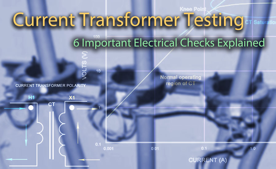
For these reasons and more, it is crucial to conduct regular inspections and calibrations of current transformers and their associated instruments. There are six electrical tests should be carried out on CTs to guarantee accuracy and maintain optimal service reliability:
Contents
- Ratio Test
- Polarity Test
- Excitation (Saturation) Test
- Insulation Resistance Test
- Winding Resistance Test
- Burden Test
1. Ratio Test
The CT ratio is defined as the relationship between the primary current input and the secondary current output at full load. For instance, a CT with a ratio of 300:5 will generate 5 amps of secondary current when 300 amps flow through the primary side.
(300:5 = 60:1)
If the primary current changes, the secondary current output will change accordingly. For example, if 150 amps flow through a 300 amp rated primary the secondary current output will be 2.5 amps.
(150:300 = 2.5:5)
Unlike the voltage or power transformer, the current transformer consists of only one or very few turns as its primary winding. This primary winding can be of either a single flat turn, a coil of heavy duty wire wrapped around the core or just a conductor or bus bar placed through a central hole.
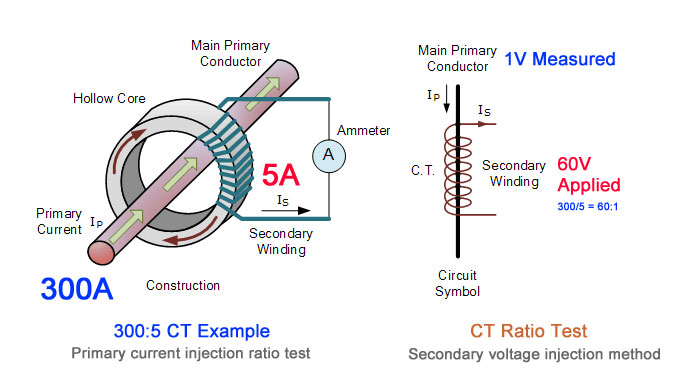
A CT ratio test can be performed by injecting a primary current and measuring the current output, or by injecting a secondary voltage and measuring the induced primary voltage. Photo: TestGuy.
The ratio test is performed to confirm that the CT’s ratio aligns with the specified values and to verify that the ratio remains accurate across different taps in a multi-tap CT. The turn’s ratio is equivalent to the voltage ratio of potential transformers and can be expressed as follows:
N2/N1 = V2/V1
-
N2 and N1 are number of turns of secondary and primary windings
-
V2 and V1 are the secondary and primary side voltage readings
Ratio tests are performed by applying a suitable voltage (below saturation) to the secondary of the CT under test while the primary side voltage is measured to calculate the turns ratio from the expression above.
DANGER: Use caution when conducting a CT ratio test and DO NOT apply a voltage high enough that would cause the transformer to saturate. Applying a saturation voltage will result in readings that won’t be accurate.
2. Polarity Test
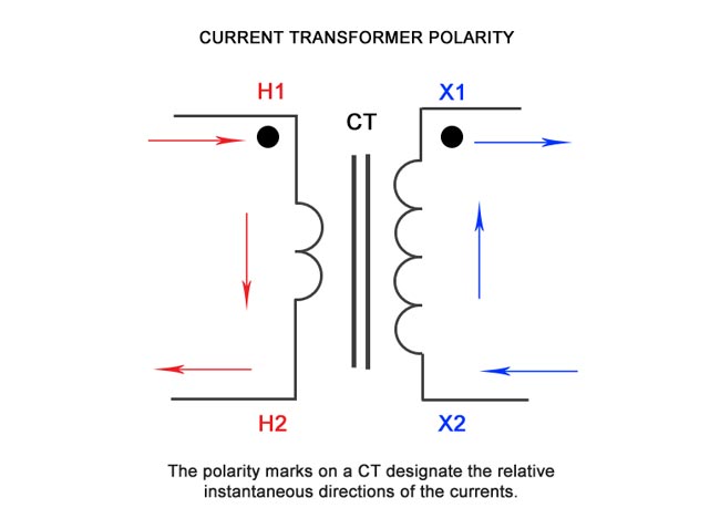
The polarity of a CT is determined by the winding direction of the coils around the transformer core (clockwise or counterclockwise) and how the leads are configured within the CT case. All current transformers are typically subtractive polarity and should bear the following designations for clear visual identification of the direction of current flow:
- H1 – primary current, line facing direction
- H2 – primary current, load facing direction
- X1 – secondary current
A CT under test is assumed to have correct polarity if instantaneous current direction for primary and secondary current is opposite to each other. Photo: TestGuy.
Polarity marks on a CT indicate the relative instantaneous directions of the currents. The polarity test confirms that the anticipated direction of secondary CT current (outgoing) is in alignment with the given direction of primary current (incoming).
Taking care to observe proper polarity is important when installing and connecting current transformer to power metering and protective relays. At the same instant of time, that the primary current is entering the primary terminal the corresponding secondary current should be leaving the similarly marked secondary terminal.
A CT under test is assumed to have correct polarity if instantaneous current direction for primary and secondary current is opposite to each other. CT Polarity is critical when CT’s are being used together in single-phase or three-phase applications.
Most modern day CT test equipment is capable of performing the ratio test automatically using a simplified test lead setup and will display polarity as correct or incorrect. CT polarity is verified manually by utilizing a 9V battery and analog voltmeter with the following test procedure:
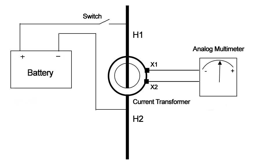
Markings on current transformers have been occasionally misapplied by the factory. You can verify the polarity of a CT in the field with a 9V battery. Photo: TestGuy.
CT Polarity Test Procedure
-
Before conducting the test, it is essential to disconnect all power sources. Then, connect the analog voltmeter to the secondary terminal of the CT that is to be tested. The positive terminal of the meter should be linked to terminal X1 of the CT, while the negative terminal should be connected to X2.
-
Pass a piece of wire through the high side of the CT window and momentarily establish contact by connecting the positive end of the 9-volt battery to the H1 side (often indicated with a dot) and the negative end to the H2 side. It’s important to avoid continuous contact, as this could result in a short circuit of the battery.
-
When the polarity is correct, the brief contact will result in a minor deflection of the analog meter in the positive direction. If the deflection is negative, it indicates that the polarity of the current transformer is reversed. In this case, the terminals X1 and X2 should be switched, and the test can be subsequently conducted.
Note: Polarity becomes irrelevant when connecting CTs to ammeters and voltmeters. Polarity is only significant when connecting CTs to devices such as wattmeters, watt-hour meters, varmeters, and induction-type relays. To uphold polarity, the H1 side of the CT should face the power source, with the X1 secondary terminal serving as the polarity connection.
3. Excitation (Saturation) Test
When a CT is “saturated,” the magnetic path within the CT behaves like a short circuit in the transmission line. This causes most of the energy supplied by the primary winding to be diverted from the secondary winding and utilized to generate a magnetic field inside the CT.
Saturation testing for a current transformer determines the rated knee point according to IEEE or IEC standards. This knee point signifies the point at which the transformer can no longer produce current in proportion to its specified ratio.
Excitation tests involve applying an AC voltage to the secondary winding of the CT and incrementally raising the voltage in stages until the CT reaches saturation. The “knee” point is determined by noting a minor voltage increase that results in a substantial rise in current.
The test voltage is gradually reduced to zero to demagnetize the CT. The test results are graphed on a logarithmic (log-log) scale and assessed by examining the transition period between normal operation and saturation.
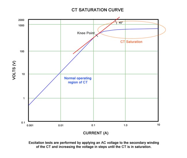
Excitation tests are performed by applying an AC voltage to the secondary winding of the CT and increasing the voltage in steps until the CT is in saturation. Photo: TestGuy.
The excitation curve around the points where current jumps up for a small increase of voltage; is very important for comparison of curves with published curves or similar CT curves. The excitation test results should be compared with published manufacturer’s data or previous recordings to determine any deviations from previously obtained curves.
IEEE defines the saturation as “the point where the tangent is at 45 degrees to the secondary exciting amperes”. Also known as “knee” point. This test verifies that the CT is of correct accuracy rating, has no shorted turns in the CT and no short circuits are present in the primary or secondary windings of the CT under test.
4. Insulation Resistance Test
During a comprehensive CT test, it is essential to assess the insulation between the current transformer windings and ground for dielectric strength. Three tests are conducted to evaluate the insulation condition of the CT under test:
-
Primary to secondary: Checks the condition of the insulation between high to low.
-
Primary to ground: Checks the condition of the insulation between high to ground.
-
Secondary to ground: Checks the condition of the insulation between low to ground.
Insulation resistance readings should remain fairly constant over a period of time. A sharp dip in trending of insulation resistance values point towards insulation degradation and further investigation is required to diagnose the problem.
Insulation tests on current transformers with ratings of 600V or less are typically conducted at 1000VDC. Before performing the test, it’s important to short-circuit the primary winding of the CT under examination by connecting H1 and H2, and subsequently short-circuit the secondary winding by connecting X1 and X2-X5.
Remove the neutral ground and isolate the CT from any associated burden. After the windings are shorted, the CT will be a three terminal specimen.
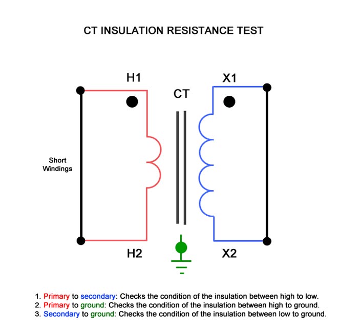
Three insulation resistance tests are performed to determine the condition of the insulation of the CT under test. Photo: TestGuy.
Insulation resistance test values for CTs should be compared with readings obtained in previous tests. Significant deviations from historical readings warrant further investigation.
ANSI/NETA MTS-2023 Table 100.5 Specifies a minimum insulation resistance of 500 Megohms at 1000VDC for dry transformer coils rated 600V or less. Reference Section 7.10.1 for more information.
The minimum insulation resistance that is generally accepted is 1 Megohm. Any reading in Megohms is considered to be a good insulation, however, it’s the trending of insulation test results that gives the true condition of CT insulation.
Insulation readings are greatly affected by the specimen temperature. Should a reading be compared to previously taken readings, proper correction factors need to be applied, if taken under different temperature conditions before drawing any conclusion.
5. Winding Resistance Test
The DC winding resistance measurement is an important measurement in accessing the true condition, state and accuracy of a CT. Winding resistance in a CT will change over a period of time depending on the specimen age, use, external conditions and loading effect.
It is recommended to measure DC winding resistance periodically on a single tap or multi tap CT and trend the values. A high precision low resistance measurement circuit is required to obtain this small winding resistance.
The winding resistance of a current transformer is found by dividing the voltage drop across the winding (measured from dc millivoltmeter) with the applied dc current through the winding. The CT should be demagnetized after the completion of winding resistance test.
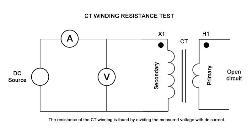
Measure CT winding resistance by passing a DC current through the winding and measure the voltage drop. Divide the measured voltage by the measured current. Photo: TestGuy.
Tip: Run a saturation test to demagnetize the CT at the completion of all winding resistance tests.
6. Burden Test
The burden of a current transformer can be described as the overall impedance in ohms across the secondary output terminals. This total burden encompasses the impedance presented by watt-hour meter coils, relay current coils, contact resistance, terminal blocks, wire resistance, and test switches used in the secondary loop.
Each current transformer has a secondary burden when connected in a relay or metering circuit. CT’s are expected to provide the secondary output current based upon their accuracy class.
If a current transformer is not appropriately sized according to the secondary loop burden, it can lead to a reduction in CT secondary current. Burden testing is important to confirm that the CT is delivering current to a circuit within the limits of its burden rating.
The burden test is also useful in ensuring that the CTs are:
- Not energized with shorting devices installed (if used for metering or protection).
- Not left with an open circuit when not used.
- Connected with a single ground point.
- Secure, and all connections are tight.
To measure the burden, inject the rated secondary current of the CT from its terminals toward the load side, while isolating the CT secondary with all connected loads. Then, monitor the voltage drop across the injection points as well as at various points throughout the circuit, including those to ground.
This method is time consuming, but only requires a voltage source, a resistance, and a voltmeter. Measuring the voltage drop at the source combined with ohms law will give us the burden impedance. Analyzing the voltage drop patterns throughout the circuit confirms the wiring is correct.
Current transformer burdens are commonly specified in VA (volt-amperes). The burden test is conducted to confirm that the CT can deliver a specific current into a known burden while preserving its declared accuracy. Typically, a burden test is carried out at the full rated secondary current value, such as 5A or 1A.
How to calculate CT Burden
Depending on their accuracy class, current transformers are divided into two groups: Metering and Protection (Relay). A CT can have burden ratings for both groups.
Metering CT’s are typically specified as 0.2 B 0.5
The last number specifies the Burden in ohms. For a CT with secondary current of 5 A the VA burden rating can be calculated as:
VA = Voltage * Current = (Current) 2 * Burden = (5)2 * 0.5 = 12.5 VA
Relaying CT’s are typically specified as 10 C 400
The last number specifies the maximum secondary voltage at 20 times the rated secondary current without exceeding the 10 % ratio error. For a CT with secondary current rated at 5 A, 20 times rated current secondary current would give a burden of 4 ohms.
Burden = 400 / (20*5) = 4 ohms
Burden in VA can be specified as:
VA = Voltage * Current = (Current) 2 * Burden = (5)2 * 4 = 100 VA