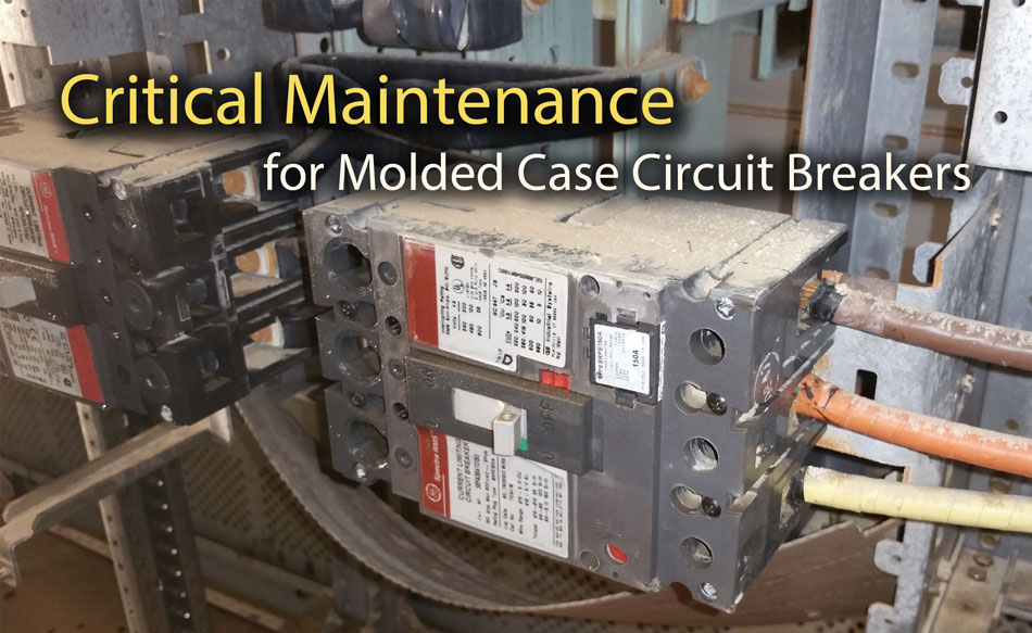
Molded-case circuit breakers (MCCB) are switching devices commonly found inside panelboards, switchboards, motor control centers, control panels, combination starters, individual enclosures, and bus duct plug-in units. Depending upon the application and required protection, an MCCB will use one or a combination of different trip elements that protect against thermal overloads, short circuits, and ground faults.
Overcurrent devices like molded case circuit breakers should be maintained in accordance with the manufacturer’s instructions or industry consensus standards, such as NFPA 70B and NETA MTS. When performed as part of a greater preventive maintenance plan, these simple inspection procedures can help ensure that molded case circuit breakers provide reliable circuit protection.
Note: Molded case circuit breaker enclosures should never be opened and generally do not require internal maintenance unless specified by the manufacturer.
Tighten Bolted Connections
The compression screws (lugs) or bus connectors of a MCCB should be checked for tightness periodically using a calibrated torque wrench. Manufacturers will typically include a label or marking that indicates the recommended torque in lb-ft.
NETA testing standards also specify recommended torque values based on the connector size and metal composition. Lug terminals and mounting bolts should never be tightened while a circuit breaker is energized.
Exercise Periodically
Molded case circuit breakers should be manually operated at periodic intervals to ensure smooth operation and that the internal lubrication is kept evenly spread within the operating mechanism.
Neglected circuit breakers can slow down or seize up over time, failing to properly clear a circuit when an electrical fault eventually occurs. Lack of exercise is one of the most common circuit breaker failures, which is why open-close operations are a critical part of routine maintenance plan.
Thermography (IR) Inspection
The heat produced from high electrical resistance typically precedes electrical failures. For this reason, infrared scans are an essential measure for troubleshooting, diagnostics, and preventive maintenance in electrical power distribution applications.
Molded case circuit breakers can be observed throughout the year with an IR camera to monitor for loose connections and uneven heating. If signs of arcing or excessive heating are present, the connections should be removed and thoroughly cleaned.
Related: Infrared Thermography for Electrical Distribution Systems
Insulation Resistance Test
As the name implies, the casing of a MCCB is specially molded using a type of glass-polyester material or thermoset composite resin. This casing is responsible for keeping the electrical conductive components isolated from the mounting points and operating mechanism. The insulation resistance test verifies the integrity of these insulating properties.
Tests should be made between pole to ground, between adjacent poles with circuit breaker contacts closed, and between phase-to-load terminal with breaker in open position. A minimum value of 1 Megohm is generally considered safe to energize but NETA standards dictate a minimum value of 100 Megohms for most low voltage applications.
Related: Insulation Resistance Test Methods, A Beginners Guide
Contact Resistance (Millivolt Drop Test)
The main contacts and primary current paths of a MCCB need to be checked periodically to detect abnormal resistance and loose pivot points within the operating mechanism. Electrical resistance of the closed circuit breaker is determined by measuring the voltage drop across the line and load terminals for each phase.
NFPA 70B recommends that large molded case and insulated case breakers be tested with DC currents of at least 100A and smaller breakers be tested at rated (or below rated) currents. High resistance values indicate abnormal conditions such as contact and/or connection erosion and contamination.
The measured values should be compared across all three phases of the device under test, or with values obtained from circuit breakers of similar size and type. Manufacturer’s may recommended values in their literature to indicate whether the contacts need to be replaced or dressed.
NETA standards specify a tolerance of 50% between phases or 1.5x the lowest measured value.
AC Dielectric Withstand Test
Hipotential tests can be performed on molded case breakers to detect a gross failure of an insulation. The pass/fail nature of this test can indicate the presence of a foreign object within an insulation system, or insufficient clearance between energized components and ground.
This test maybe conducted to verify the MCCB withstand voltage capability and is often performed while installed as part of a larger, overall switchgear test.
Sample Inspection Procedure for Molded Case Circuit Breaker
Even though molded case circuit breakers can be very reliable, they tend to gather dirt, moisture, and contaminants while in service.
Regular maintenance and inspection of a MCCB does not need to be a complicated task. Qualified persons can perform the following on a routine basis to ensure optimal service life:
-
Never perform maintenance on a circuit breaker that is energized.
-
Ensure the unit is clean and free from all external contamination.
-
Inspect the enclosure and all visible surfaces for cracks, discoloration, or other damage.
-
Check for loose connections, and tighten circuit breaker terminals and bus bar connections as required. Use the manufacturer’s recommended torque values or those specified in NETA standards. Avoid blindly torquing connections as this can lead to excessive compression on the conductors over time.
-
Manually exercise the circuit breaker by repeatedly switching the device on and off several times. Charging operations should be smooth and trip operations should be fast and “snap.” Verify function of the manual trip button.
-
Check the operating environment for high-humidity conditions as this will deteriorate the insulation system.
-
Inspect the unit for hot spots typically caused by overheating due to termination or connections being loose, high contact resistance, or inadequate ventilation. This check should be performed under normal loading conditions, prior to de-energized maintenance, to identify equipment that requires special attention.
Further Reading
- Guidelines for Inspection and Preventive Maintenance of Molded-Case Circuit Breakers Used in Commercial and Industrial Applications
- NFPA 70B: Recommended Practice for Electrical Equipment Maintenance
- ANSI/NETA MTS-2019: Standard for Maintenance Testing Specifications for Electrical Power Equipment and Systems
- Proper Application and Maintenance of MCCB’s
- A Balanced Approach to Molded Case Circuit Breaker Maintenance