Synchronism relays operate when both the bus and line voltage are equal. Photo: TestGuy.
Improper synchronization of electrical sources can have damaging effects on a power distribution system, resulting in electrical and mechanical transients that can destroy prime movers, generators, transformers and other critical components.
Synchronism (sync) relays are used to verify that the voltages on either side of a circuit breaker are in the proper phase and magnitude relationship. The relay will permit a closing operation when both the bus and line voltage are approximately normal, equal, in phase, and of the same frequency.
The primary application of the sync check relay is in situations that require verification of synchronism prior to closing a circuit breaker. These scenarios include the paralleling of a generator to a system, reestablishing an interconnection between two parts of a power system, and supervision of fast motor bus transfer schemes, high-speed reclosing schemes, etc.
Basic Sync Check Principles
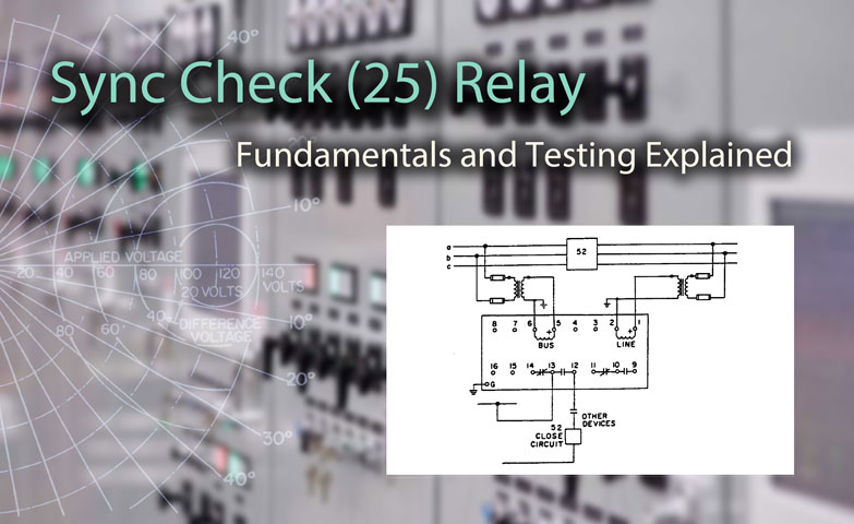
Closing characteristics of the sync check relay are determined by the magnitude of vector difference voltage setting, typically anywhere from 0-80 volts at the relay. A smaller difference voltage setting allows for a more restrictive synchronization criteria.
The time delay setting determines how long that the two sources must be synchronized before the relay output contacts will transfer. The time delay is influenced by the difference voltage setting and is commonly set in a range between 1-15 seconds.
Typical voltage difference closing characteristic. Photo: ABB.
Should the two sources fall out of synchronization before the end of the time delay, the timer will reset to zero and the output contacts will not transfer. A longer time delay setting will therefor allow a more restrictive synchronization criteria.
Frequency is another critical factor in the synchronization process that requires a slip of 0.1Hz or less between sources to obtain relay operation. Longer time delays will require sources match their frequency within this tolerance for longer as exceeding 0.1Hz will restart the time delay.
Relay manufacturers provide curves for maximum slip frequency at which closing will occur as a function of the relay’s time delay and difference voltage setting.
Modes of Operation for Sync Check Relays
Synchronism check relays may be equipped with several different operating conditions in addition to the “normal” sync check function to allow closing of the output contacts when either the line or bus is dead.
The basic options provided are:
- Hot Bus – Dead Line (HBDL)
- Hot Line – Dead Bus (HLDB)
- Combined – HBDL or HLDB
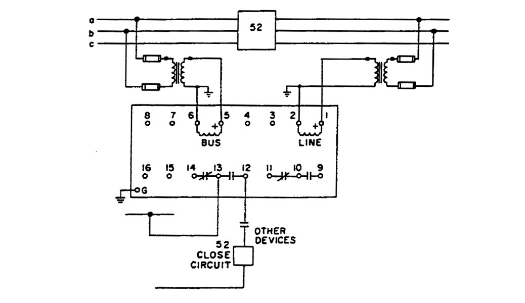
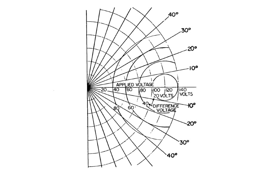
Typical connection diagram for synchronism relay (25). Photo: ABB
The pickup indicator will illuminate when the Line and Bus voltages meet the difference voltage setting criteria (or the dead-bus, dead-line conditions). The voltage levels at which the bus or line are considered “hot” is adjustable independently via the relay settings.
A typical setting would be 30 volts, with a nominal range of 0 to 120 volts. In each operating mode, if both sources are live, a normal sync check measurement is made. Sync relays with several operating modes can also be set to only monitor for normal function.
Testing and Maintenance
Testing and maintenance of protective relays always begins with a thorough visual and mechanical inspection. What to check and inspect varies depending on the type of relay (electromechanical, solid-state, or microprocessor-based).
Procedures for each type of relay are summarized in the Protective Relay Testing and Maintenance Overview.
Relay protection settings should match the most recent coordination and arc-flash study or engineered setting files. This information is often furnished on a time–current curve of the coordination study displaying the characteristics of the relay.
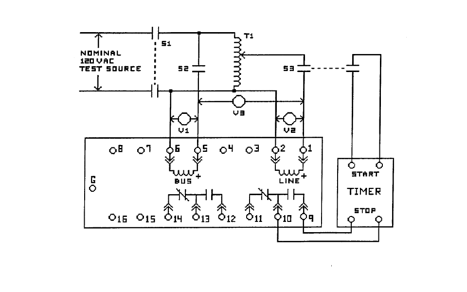
Basic test connections for Sync Check (25) Relays. Photo: ABB.
Check functional operation of each element used in the protection scheme:
- Determine closing zone at rated voltage.
- Determine maximum voltage differential that permits closing at zero degrees.
- Determine live line, live bus, dead line, and dead bus set points.
- Determine time delay.
- Determine advanced closing angle.
- Verify dead bus/live line, dead line/live bus and dead bus/dead line control functions.
Functional Testing
In addition to the inspection and testing of protective relays, it may be desirable to prove the correct interaction of all sensing, processing, and action devices as a complete unit by means of system functional tests.
Lock-out relay and block close circuits should be tested, along with relay self-test, power supply failure, and trip coil monitor alarms back to SCADA. Bus restoration and/or transfer switches should be verified as functional.
Built in test functions allow for simple verification when both sources to the relay are energized and in sync. With self-test equipped relays, pushing a button will typically simulate a loss of synchronization and return the output contacts to their de-energized position. When the button is released, the relay will pickup and start the timing process before returning the contacts to the energized position.
The self test function should never be used as a substitute for secondary-injection tests.
Upon completion of testing, control circuits and current transfer circuits should be restored to normal operation. Verify that all systems are left in normal operating mode or position, transfer and restoration schemes are enabled, and monitoring and protection devices are operational.