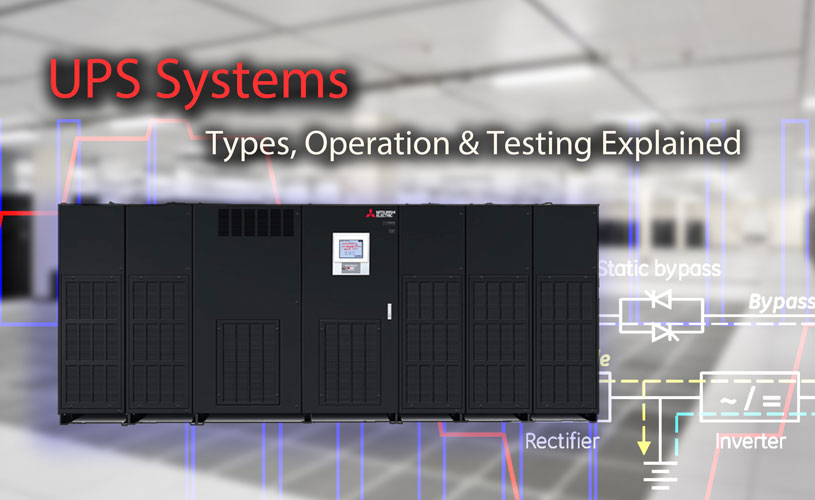
Uninterruptible Power Supply (UPS) Systems are used extensively in critical environments to support sensitive electrical equipment when there is a power loss or a significant change in the primary power source. Backup power is provided to the UPS by a string of batteries that can instantly support the load when it detects a loss or other interruption in the available power.
Once a power anomaly has been detected, the UPS control will transfer over to DC battery power and convert the output to AC via an inverter. When normal power is restored, the UPS will switch back to normal and use available power to recharge the batteries.
UPS systems are found nearly anywhere computers or other critical electronic equipment is operating. How long the UPS can sustain a load can vary, but it allows a window of time for the issue to be resolved, or in the worst case, provides an opportunity for the systems to be shut down in a controlled manner.
The type and capacity of a UPS can range anywhere from 150VA to 1500kVA. Small UPS systems can be found under a desk, powering a single desktop computer or internet router, while large UPS systems are located in data centers, powering several server racks containing hundreds of computers and other communications equipment.
General Functions of a UPS
Not only is an Uninterruptible Power Supply capable of providing emergency power, it can also be used to condition power and protect against relatively small sags, swells and surges. UPS systems can smooth out noisy power sources and provide alarms when various conditions are met.
Metering and logging functions allow status monitoring of the power supply. Communications and software can be used to automatically shutdown or restart equipment after a long power outage. Circuit breakers provide short circuit protection and a means to bypass the equipment for maintenance.
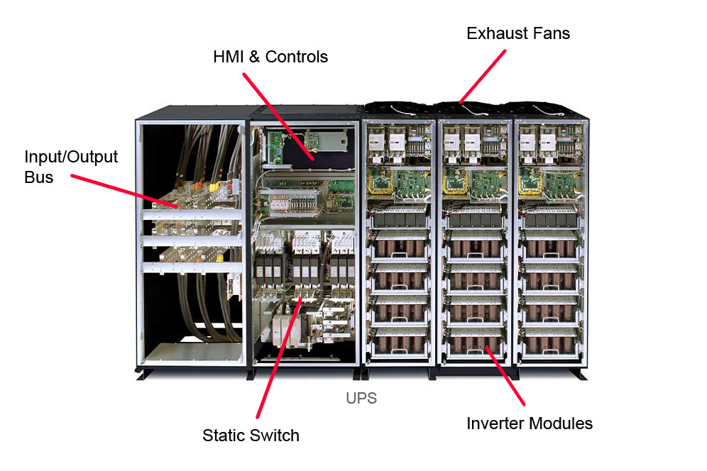
Basic Example of UPS Components. Photo: Mitsubishi Electric.
Types and Modes
Selecting the right UPS topology depends largely on three factors: the environment, the budget and the level of sensitivity of the equipment that needs to be protected. Because modern IT power supplies are built to withstand a wide range of power quality issues, a variety of UPS topologies provide some degree of protection against power loss and disturbances in the electrical system.
-
Standby (Offline) – Remains offline until power drops to an unsustainable level. Most cost effective, commonly used on desktop computer systems.
-
Line Interactive – Employs buck/boost to adjust voltage and preventing battery use as often. Found in small business infrastructure. Auto voltage regulation, useful for spikes and surges.
-
Double-Conversion (Online) – Always conditions power by double conversion. Primary source is the batteries. No transfer switch necessary, no time loss. Batteries always charge when normal power is available. This type of UPS also provides greater isolation of load.
Modern double-conversion UPS systems are capable of running in various operating modes to achieve better energy savings. Commercial AC power is supplied directly to the critical load through a continuous static switch and transfers automatically to the inverter when an abnormal condition is detected, effectively running in standby mode.
The UPS may also operate as a traditional double-conversion UPS, but selectively shift the load to fewer power modules to increase efficiency for lighter loads.
-
Online (Active) Mode: Critical load is supplied by inverter via utility AC power. Charging current is provided for batteries.
-
Energy Saver Mode: Utility power is supplied directly to critical load through a continuous static switch and transfers to online mode when an abnormal condition is detected.
-
Variable Mode: UPS operates as a traditional double-conversion UPS with selective load shifting capability.
-
Bypass Mode: Critical load is directly supported by utility power and is subject to interruptions. UPS can be serviced.
-
Battery Mode: Backup batteries provide DC power to maintain inverter operation and support critical loads.
Design and Capacity of UPS Systems
As uptime and reliability are the top priorities of a UPS, it all comes down to the integrity of the UPS to carry the load.
1050 kVA and Larger
A three phase UPS found in data centers are large, modular, freestanding units that can range from 1050kVA to 2000kVA. These systems can be as large as the switchgear equipment feeding them, with battery systems large enough to fill an entire room. Depending on the load requirements, a UPS of this size can support a critical equipment for several hours.
80 to 750 kVA
Until recently, a three phase with capacity up to 750 kVA was considered large. With the advent of the new hyperscale data centers, sizing a three phase power supply has changed. 80-750 kVA UPS products are now considered medium and are commonly, but not exclusively, utilized in medium size, or edge data centers with a 1-5 MW load range.
10 to 80 kVA
A three phase uninterruptible power supply in the 10-80 kVA range will normally be used to back up smaller size enterprise operations, server rooms or IT closets. It’s a modular three phase power supply with the ability to expand as needed. These units are generally small enough to mount directly on racks alongside server equipment.
1500 VA
A single phase uninterruptible power supply can support small critical devices during an electrical power outage. This type of unit is ideal for personal computers, home office electronics, networking equipment, and SmartHome devices. These may also be employed in switchgear applications to provide control power for the HMI and other important communications.
Theory of Operation
Regardless of the typology, a UPS resorts to battery backup power in the event of a problem. When incoming utility power drops below or surges above safe voltage levels, the UPS switches to DC battery power and then inverts it to AC power to run connected equipment.
Double conversion UPS systems are the most reliable and most widely used in critical data centers for providing power to large server equipment. This conversion process (AC-DC-AC) and filtering smooths out events such as spikes, sags, surges, and electrical noise, ensuring the final output is a pure sine waveform. There are four main components in any online double conversion uninterruptible power supply (UPS) system:
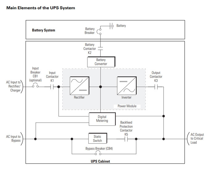
Main Elements of a UPS System. Photo: EATON.
1. Rectifier
The main function of the rectifier is to convert AC power into DC power. It achieves this with the use of diodes, which only allow the flow of electricity in one direction.
Either the positive or negative half of the AC wave is passed, while the other half is blocked. This is known as half-wave rectification because only one peak of the AC wave is usable.
When multiple diodes are arranged to form a bridge, both polarities of the AC waveform can be converted to form a more consistent voltage. This process is known as full-wave rectification because both peaks of the AC wave are passed.
Single-phase rectifiers are commonly used in smaller domestic equipment such as computer power supplies. Most industrial and high-power applications utilize three-phase rectifier circuits which produce a constant “ripple” voltage. Thyristors are commonly used in place of diodes to create a control circuit that can regulate the output voltage.
In addition to converting AC voltage to DC voltage, the rectifier inside of a UPS is responsible for recharging the batteries and maintaining proper float voltage. UPS rectifiers can accept wide input voltage fluctuations, meaning the system can handle overloads or surges without having to engage the batteries.
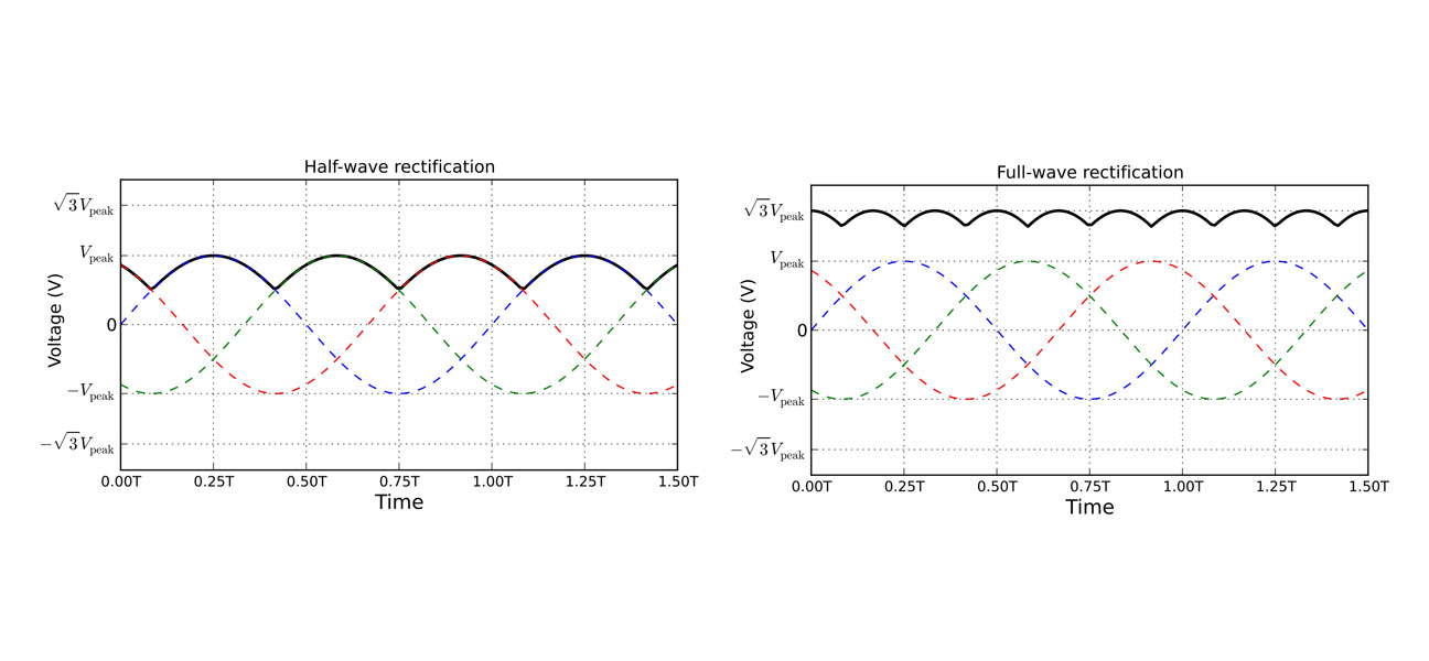
Have-wave vs. Full-wave rectifiction. Photo: Wikimedia.
2. Inverter
The reverse operation of rectification is inversion, where DC voltage is converted back to AC using transistors to rapidly switch currents on and off, creating pulsed DC in opposite polarities. The amount of current flow occurring per square wave segment can be controlled by changing how long the switches are closed. The more segments per pulse will result in a cleaner wave - a process known as pulse-width modulation.
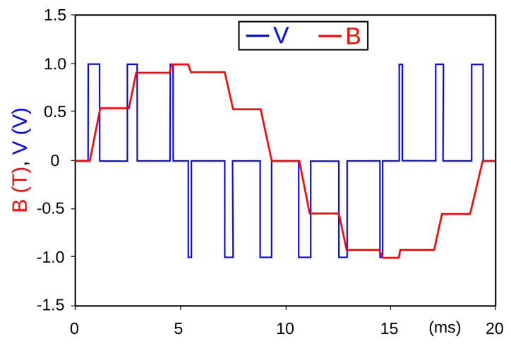
Pulse-Width Modulation: The more segments per pulse will result in a cleaner wave.
3. Static Bypass
When an overload or fault occurs within a UPS, the static bypass switch automatically connects load to the main power supply. The static bypass is a safeguard against internal failure and is capable of bypassing the rectifier, batteries, and inverter. When connected directly to utility power, critical loads will not receive filtered or conditioned power as normal in an online double-conversion UPS.
The UPS automatically switches to Bypass mode if it detects an overload, load fault or internal failure. This can subject the connected equipment to power interruptions such as brownouts and dangerous power surges, but it does allow equipment to continue functioning while the UPS is repaired or replaced. It also provides a window to shut down critical loads in an orderly manner.
4. Maintenance Bypass
To provide a separate means of isolation, the UPS system may be configured with a maintenance bypass switch. This allows service technicians to safely divert normal power to the critical loads while the UPS is temporarily removed from service for maintenance.
The load will be subjected to power interruptions during this period. Depending on the critical nature of the facility, a redundant or parallel UPS system may be employed to support sensitive loads while the primary system is taken down for maintenance.
Batteries
Although every single component in the UPS is critical to its operation, the batteries are the workhorse that supply temporary emergency power when the main supply fails. The UPS rectifier or separate charging system ensures the batteries are always at peak capacity.
The number of batteries required will depend on the DC voltage of the UPS. For smaller UPS systems, the batteries are often internal to the unit. In larger UPS systems, the batteries are often housed in their own standalone cabinets as part of a large string.
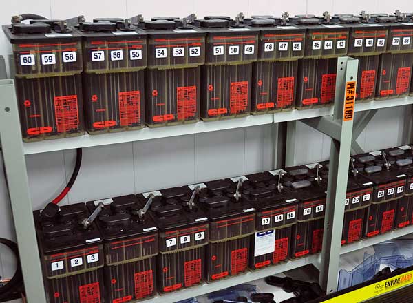
The main objective of a battery system is to provide standby and emergency power to critical equipment during an AC outage. Photo: Paul Chernlkhowsky (Flickr CC)
UPS battery strings are connected in series to achieve the necessary voltage, and if a single battery in the string fails, the entire string will be lost. For this reason, it is critical that periodic inspections be performed on UPS batteries.
There are several tests that can be performed to monitor the voltage level, impedance, and electrolyte quality of the cell. Batteries are extremely dangerous because they are a constant source of energy that cannot be de-energized. When connected in a large string, the risk of danger increases dramatically.
Startup Procedure for UPS
Bringing a UPS system online requires a specific sequence of events, which may vary in scope by manufacturer. Before starting any UPS, ensure all installation tasks have been completed and preliminary startup/acceptance testing has been performed by authorized service personnel.
The initial startup for large industrial UPS systems are typically performed by the equipment manufacturer. This process verifies all electrical interconnections and operating procedures to ensure the installation was successful and the system operates as designed.
Single UPS Startup
-
Verify that the UPS input circuit breaker is in the open position.
-
Close the UPS Bypass input feeder circuit breaker. This will energize the static switch and provide unconditioned power to the output.
-
Close the UPS input circuit breaker. This will provide power to the rectifier and inverter.
-
Observe the UPS control panel display. Verify the UPS status is offline or not protected.
-
Close the battery circuit breaker. This will connect the backup batteries to the DC bus inside the UPS.
-
Verify the presence of no alarms and use the control panel to bring the UPS online. The rectifier and inverter will turn on and switch to protected power once reaching full voltage. The UPS display should indicate that the UPS is online and the load is protected.
Single UPS Shutdown
-
Shutdown critical loads in an orderly manner.
-
Transfer the UPS to bypass using the manufacturers specified operating procedure.
-
Perform a load off procedure in accordance with equipment operating instructions. The input, output, battery, and bypass contactors open, and the power module is turned off. Power may still be present inside the UPS cabinet until the upstream input feeder circuit breaker is opened.
-
Open the ups input and battery circuit breakers.
UPS Maintenance Procedures
Periodic inspection and performance checks of a UPS system is essential to keep it running properly and trouble-free. A quality UPS design should feature repairable parts and components that are located for easy removal, with very little disassembly. This allows service technicians to perform routine maintenance and servicing quickly, minimizing the time critical loads remain unprotected.
Warning: UPS systems are designed to supply power even when disconnected from the utility power source. The internal components of a UPS should be considered unsafe until the DC power source is disconnected and the capacitors are discharged. At least five minutes is required for capacitors to bleed off before attempting to work inside of a UPS module. Batteries are stored energy devices and cannot be de-energized, so extra care must be taken when working with these components.
1. Basic Maintenance
The area surrounding the UPS should be checked daily, ensure adequate clearance around the unit and verify unrestricted airflow at the air intakes and exhaust openings. The operating environment must be kept suitable for the equipment and the unit should be monitored for alarms or other abnormal status.
The air filters off a UPS should be checked monthly and changed as necessary. This is also a good time to document parameters such as system events, metering, and setup configuration. Verify the correct time/date, communications ID, etc.
2. Periodic Maintenance
Inspections must be made by qualified individuals at regular intervals to determine if components wiring, and connections exhibit evidence of overheating. Bolted connections and circuit breakers must be checked for high resistance using an infrared camera when the UPS is online, or by taking low-resistance measurements when the system is offline.
The unit should be cleaned periodically using manufacturers approved methods. All electrical and mechanical interlock systems should be inspected for correct operation and sequencing.
Test static transfer from inverter to bypass and back. Use normal load, if possible. A power quality meter can be connected to capture waveform snapshots of the UPS input and output and verify internal metering components.
The undervoltage trip level on inverter input breaker should be tested and set according to manufacturer’s published data. Alarm circuits should also be verified as functional. Additional infrared scans can help identify anomalies in capacitor banks and diode circuits while the UPS is functional and operating under at least 40% capacity.
3. Battery Maintenance
Performing regular inspections on battery systems presents a unique challenge from other electrical power systems in that you cannot simply turn them off for maintenance or corrective action.
Specific Gravity
The specific gravity of the battery electrolyte can determine the state of charge. The higher the specific gravity of the electrolyte, the higher the state of charge. While useful, the specific gravity is not traditionally known to provide much value in determining impending battery failure. IEEE 450 recommends specific gravity be performed on 10% of cells quarterly (5.2.2) and all cells yearly (5.2.3).
Float Voltage
Measuring float voltage is one of the more traditional methods of testing a battery, but it’s important to understand that a correct cell voltage doesn’t indicate anything except that the cell is fully charged.
Because the sum of all cell voltages must equal the battery charger setting, the lower voltage cells must be counteracted by overcharging the cells in better condition, which leads to higher operating temperatures. IEEE recommends battery float voltage be checked quarterly (5.2.2).
Bolted Connections
Validate intercell connection resistance using a low-resistance ohmmeter. IEEE 450-2010 (5.3.1) specifies that the variation of intercell connection resistance between batteries cannot be more than 20% above the installation value or ceiling value set by the system designer. It’s recommended that intercell connectors be measured annually per IEEE 450-2010 Section 5.2.3.
Internal Impedance
Battery Impedance tests are performed to determine the internal ohmic value and indicate the overall health of a battery. A lower internal resistance generally indicates a higher capacity; therefore an increase in internal resistance over time can indicate declining battery capacity, or degradation.
Related: 3 Simple and Effective Tests for Battery Systems
4. Other Maintenance
Complete electrical and functional testing of an emergency system may also include equipment such as automatic transfer switches and emergency generators. Each component in the system must be checked to help ensure proper operation should an unexpected power failure occur.
Related: Transfer Switch Testing and Maintenance Guide