Most failures of electrical power equipment result from a breakdown in the insulation system. To minimize failures, it is recommended to conduct periodic maintenance testing of the insulation to determine its rate of deterioration.
Power factor tests are employed to measure dielectric losses, which are indicative of the wetness, dryness, or deterioration of electrical insulation.
Power factor is defined as the cosine of the phase angle between voltage and current. In an ideal insulation scenario, the phase angle is 90°. However, in practice, no insulation is ideal; each has a certain amount of loss, and the total current leads the voltage by a phase angle less than 90°.
How is Power Factor Measured?
Measuring insulation power factor is achieved by calculating the ratio of the capacitive or “charging” current (measured in volt-amperes) to the resistive or “leakage” current (measured in watts).
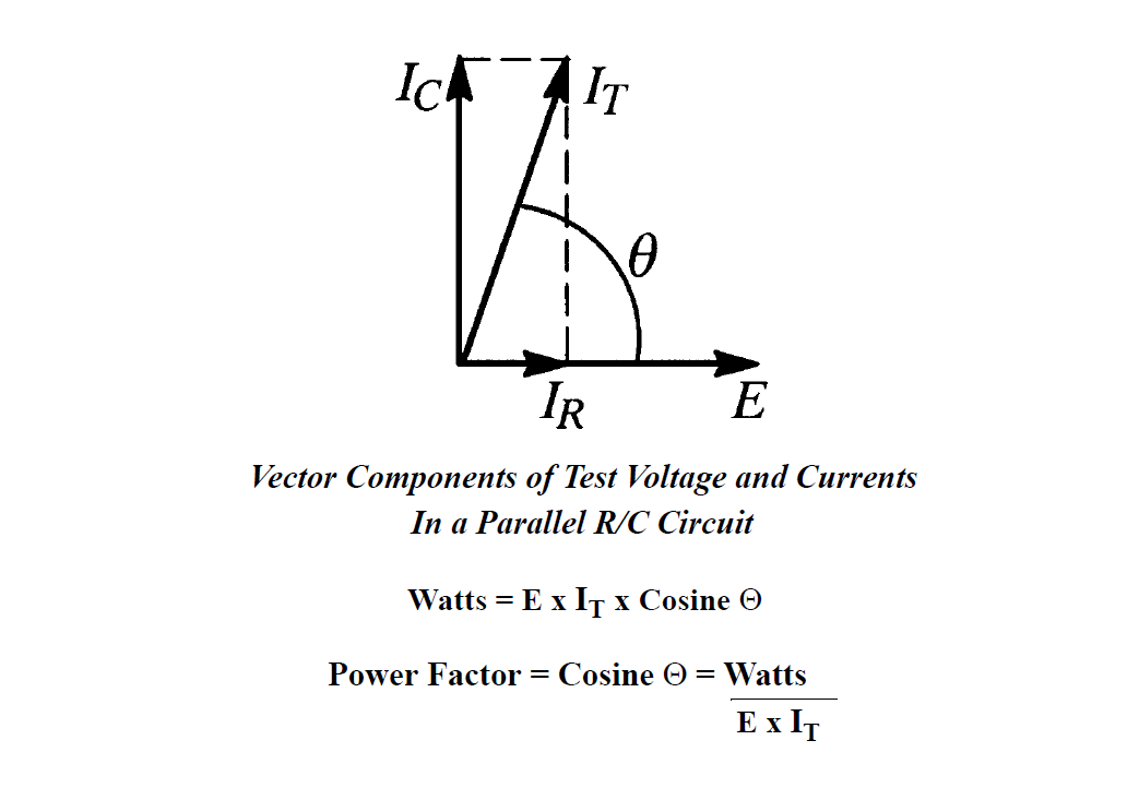
Vector Components of Power Factor Test Voltage and Current. Photo: Doble Engineering.
Testing power factor is a means of measuring the integrity of the insulation. The smaller the power factor, the better the insulator, making this one of the best testing techniques for predictive and preventive maintenance.
Power factor testing enables the detection of equipment insulation problems without the need for internal visual inspection. The result is a significant decrease in maintenance costs and downtime.
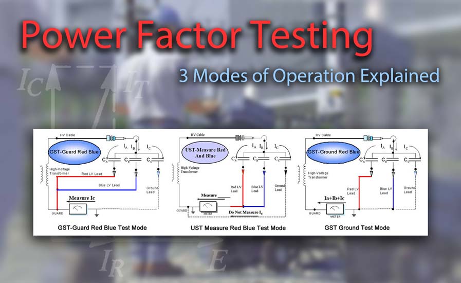
The power factor test set utilizes an AC voltage and comes with three basic modes of operation:
- GST - Grounded Specimen Test
- GST Guard Mode - Guarded Specimen Test
- UST - Ungrounded Specimen Test
Power Factor Test Set Leads
When considering the three different modes of operation, it is important to understand which test leads are associated with each mode. Power factor test sets have four leads for connecting to the device under test:
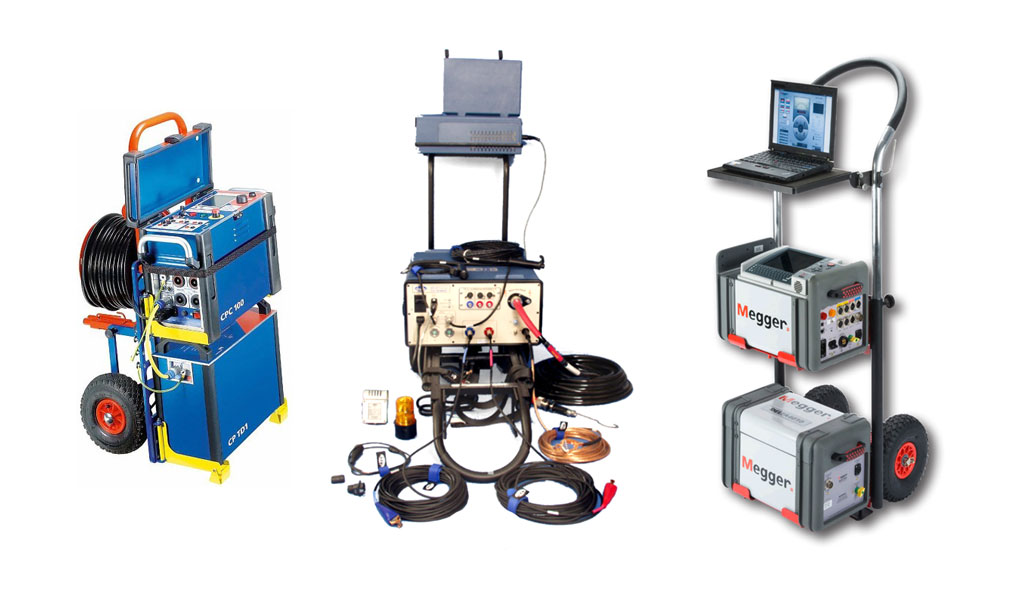
Power factor test sets have four different leads for connecting to the device under test. Photo: TestGuy
-
High Voltage Output Lead - Supplies the voltage necessary to produce the test current. Not specific to any mode of operation. Power factor testing is typically performed at 10 kV, or values equivalent to 10 kV are obtained.
-
Ground Return Lead (GST) - Measures current flowing through the ground path.
-
Red/Blue Leads (UST) - Used to guard out current not flowing through the ground path. Examples of this include the leakage between the high-side winding and low-side winding of a transformer or the current leaking between the line side and the load side of an open circuit breaker. Of the two UST leads, only one is actually used in over 95% of practical applications.
Three Modes of Power Factor Testing
When you break it all down, it’s quite simple: There are two paths of leakage current returning to the test set—ground or guard.
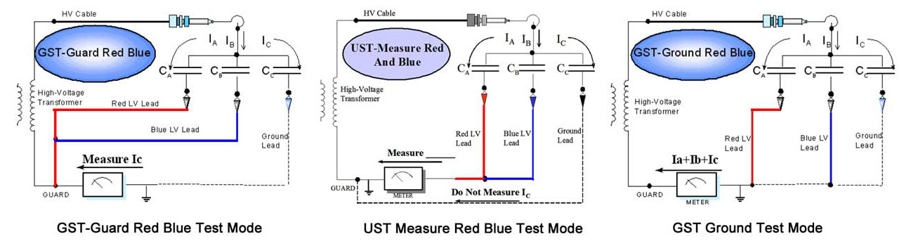
When considering the three different modes of the power factor test set, it is important to understand which test leads are associated with each mode. Photo: Doble.
The GST Guard test measures the total current leaking to ground only. The power factor test set ignores current flowing through the red or blue lead.
Conversely, in UST mode, ground is considered guard since grounded terminals are not measured. During the UST test, the only current being measured by the test set is the current flowing on the red or blue lead. Any current flowing to a grounded terminal is bypassed directly to the AC source return and is eliminated from the measurement.
UST mode is used to measure insulation between two ungrounded terminals of the apparatus, isolating an individual section of insulation for testing without measuring other connected insulation.
In the last mode of operation, the GST mode, both leakage paths (ground lead and the red or blue lead) are measured by the test set. The current, watts loss, and capacitance parameters of the UST and GST Guard tests should equal the parameters in the GST test. This provides the overall condition or power factor of the test specimen.
If the sum of the UST and GST guarded parameters does not equal the GST parameters, then either the test set is malfunctioning, or the test leads are configured incorrectly.
References
- Theory and Application of Power Factor Testing
- Power Factor Insulation Diagnosis
- The Value of Power Factor Testing
- Power Factor Testing: Why Test? - Emerson Network Power (02-yt-08)