IEC 61850 is a standard which defines communication between protection and control devices in an electrical substation. This includes protocols such as Sampled Values and GOOSE messaging, accompanied by a structured framework for automation.
At its core, IEC 61850 provides a systematic approach to modeling the entirety of a substation, covering both primary and secondary equipment. Additionally, it outlines the necessary engineering processes and methodologies for implementing automation functions within substations.
The standard can be applied in all areas of substation automation such as control and monitoring of industrial facilities and distributed generation. In this article, we breakdown the essentials of IEC 61850, exploring its foundation, key protocols, and the hierarchical structure of substations.
Contents
- Purpose and Scope
- Communication Protocols
- Data Models
- Logical Nodes
- Data Publisher and Subscriber
- Important Terms
- References
Purpose and Scope
The IEC 61850 standard was developed with several key objectives in mind:
1. Achieving interoperability between substation devices
By establishing common communication protocols and data models, IEC 61850 facilitates seamless interaction and data exchange among different devices within a substation, regardless of the manufacturer.
2. Reducing the amount of hardware needed within a substation
Through its standardized approach to communication and control, IEC 61850 enables the consolidation of functions previously performed by multiple proprietary devices into fewer standardized components, thereby reducing the overall hardware requirements of a substation.
3. Making substation projects faster and easier
By providing a standardized framework for substation design, configuration, and implementation, IEC 61850 streamlines the engineering and commissioning processes, leading to quicker project completion and reduced complexity.
4. Facilitating faster and easier expansion of the substation in the future
The modular and scalable nature of IEC 61850-compliant systems allows for easier integration of new devices and functionalities into existing substations, enabling seamless expansion and upgrades as operational requirements evolve over time.
Communication Protocols
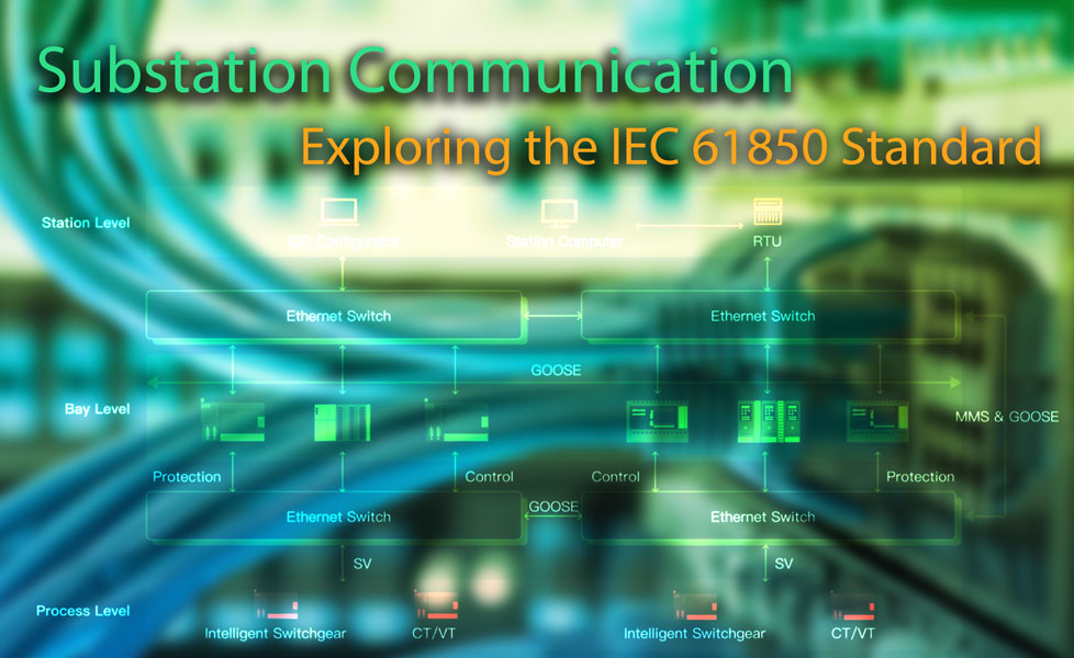
Communication protocols in IEC 61850 serve the purpose of ensuring interoperability and seamless communication between intelligent electronic devices (IEDs) in substation automation systems. These protocols define the rules and standards for data exchange, device configuration, and system management, allowing different devices from various manufacturers to communicate effectively and operate together within the substation.
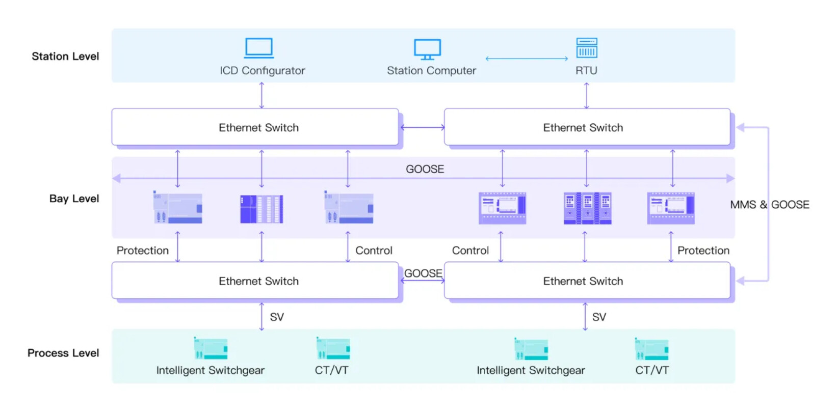
IEC 61850 Network Level Overview. Photo: ABB
The IEC 61850 standard encompasses three main protocols:
1. Client/Server (TCP/IP Protocol)
This protocol enables the routing of data messages based on the IP addresses of devices. In this setup, a protective relay typically functions as the server, providing data to clients such as the substation Human-Machine Interface (HMI) or gateway. Through this mechanism, clients can request and receive data from server devices within the substation network.
2. GOOSE (Generic Object Oriented Substation Event)
GOOSE messaging is widely adopted within IEC 61850. It serves as a mechanism for peer-to-peer communication between Intelligent Electronic Devices (IEDs), often involving protective relays.
Messages transmitted via GOOSE are exceptionally fast, with response times typically less than 4 milliseconds. These messages are sent periodically on a heartbeat interval and immediately upon any relevant state change. GOOSE messaging offers faster communication compared to traditional contacts I/O methods.
3. Sampled Values
Sampled Values provides a means to digitize and transmit primary equipment values across the network. This protocol allows for the sampling of values at a high frequency, typically around 80 samples per cycle.
These digitized values are then published to the network, where subscribing IEDs can receive and process them, converting them into operational quantities. This protocol facilitates real-time monitoring and control of primary equipment within the substation.
Data Models
In IEC 61850, data models serve to construct a software representation of physical substation devices, such as circuit breakers and metering equipment. These models are organized into distinct logical groups, including devices, nodes, classes, and data.
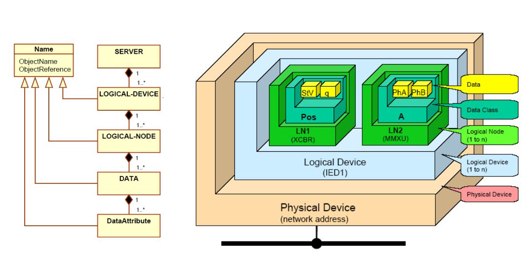
1. Physical Device (Network Address)
The physical device corresponds to the network address of a specific piece of equipment within the substation. It provides a unique identifier for communication purposes.
2. Logical Device (Protective Relay)
The logical device represents a functional grouping of related equipment, often centered around a specific task or function within the substation. For instance, a protective relay may be designated as a logical device.
3. Logical Node (Connected Device)
Logical nodes are individual functional elements within a logical device. These nodes represent specific components or functionalities of the device, such as sensors, actuators, or controllers.
4. Data Class (Collection of Data)
Data classes group related data attributes together. They provide a structured framework for organizing and managing data within logical nodes. Common data classes include those related to measurements, settings, and control commands.
5. Data (Attributes and Values; Status/Opened/Closed)
Data within IEC 61850 comprises attributes and their corresponding values. Attributes represent specific characteristics or properties of the equipment, such as status (e.g., open or closed) or measurement values. These attributes are assigned values that reflect their current state or properties.
Logical Nodes
Each functional element within the data model is defined as a logical node (LN). These nodes are organized into logical devices (LDs), with each LD capable of housing multiple logical nodes. The logical device, often represented by an Intelligent Electronic Device (IED) such as a protective relay, serves as a central unit for managing and coordinating the functionality of its constituent logical nodes.
The logical nodes within IEC 61850 are standardized with a prefix to represent the type of device. If the node begins with P, for example, it will be protection related.
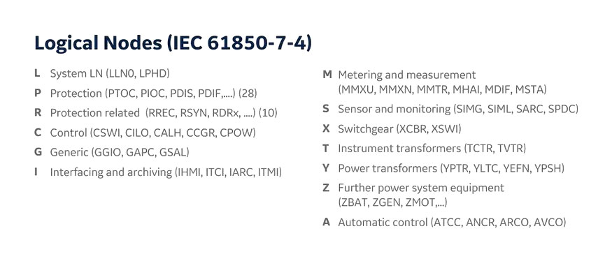
Logical nodes serve as descriptors for the substation, encapsulating various functions essential for modeling the power system and facilitating data communication among devices. Within a relay or Intelligent Electronic Device (IED), these logical nodes are utilized to represent and coordinate specific tasks or functions of the substation infrastructure.
Data Publisher & Subscriber
In the context of IEC 61850, the concepts of data publishing and subscribing are integral to the exchange of information within a substation network. This framework allows each IED to pick and choose the data that is important to its function.
1. Data Publishing
Data publishing involves the transmission of information from a device or Intelligent Electronic Device (IED) onto the network. This can encompass various types of data, including:
-
Peer-to-peer messaging (GOOSE): Messages exchanged directly between IEDs for rapid communication of critical events or status changes.
-
Client-server messaging (HMI): Data provided by an IED to be accessed by human-machine interface (HMI) devices for monitoring and control purposes.
-
Instantaneous sampled values (process bus): Real-time measurements of electrical quantities sampled from primary equipment and transmitted onto the network.
-
Reporting (metering data for SCADA): Regularly scheduled reports containing metering data for supervisory control and data acquisition (SCADA) systems.
2. Data Subscribing
Data subscribing involves configuring devices or IEDs within the network to receive and utilize published data. Devices interested in specific types of data subscribe to relevant data streams. For instance:
-
A feeder protection relay may publish its operational status and protective trip signals onto the network.
-
Another relay within the network can subscribe to this data to monitor the status of the feeder and take appropriate actions based on received information.
Messages in the IEC 61850 network are multi-cast, meaning they broadcast to all ports within the configured network. This ensures that any devices interested in the transmitted messages can subscribe and access the relevant data for their operation or monitoring purposes.
IEC 61850 Interface Levels. Photo: GE Industrial.
Important Terms
Station Level (Network Interface)
The station level represents the highest tier in the substation hierarchy and serves as the interface to the wider network. It encompasses devices such as network gateways and operator workstations responsible for overall system management and communication with external networks.
Bay Level (Relays/Logical)
The bay level comprises relays and logical devices responsible for localized control and protection functions within specific equipment bays or sections of the substation. These devices execute protection schemes and relay commands based on received data.
Primary Equipment (Process Interface/Sampled Values)
Primary equipment refers to the physical assets within the substation responsible for the direct handling and manipulation of electrical power, such as transformers, circuit breakers, and busbars. The process interface facilitates communication between primary equipment and the digital control system, often involving the transmission of sampled values representing electrical parameters.
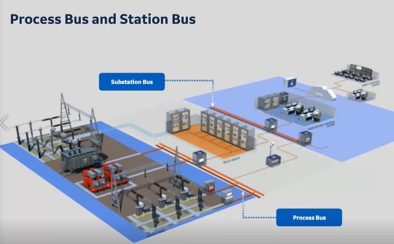
Process Bus
The process bus refers to the communication network used for transmitting sampled values from merging units (process interface) associated with primary equipment. This bus facilitates the real-time exchange of high-resolution data necessary for precise control and monitoring of the power system.
Station Bus
The station bus interconnects devices at the station level, including relays, operator workstations, network gateways, and substation HMIs. It enables the transmission of control signals, status information, and GOOSE messages between devices within the substation. Functions such as reclose initiation and breaker failure detection can be coordinated via the station bus.