Optical fiber cables transfer data signals in the form of light, which travel significantly faster and farther than those used in traditional conductors. Fiber optic cables are a top choice for high-speed communication systems and can also serve as sensors to measure and monitor various quantities.
In the electrical power industry, optical fiber products are extensively used in communication with protection, monitoring, and control devices. Modern transformers, electric motors, switchgear, and more all incorporate fiber optic cables to capture and transmit crucial data between coordinated equipment and power grids.
Optical fibers can function as sensors to measure temperature, pressure, and arc-flash events by modifying a fiber so that the property being measured modulates the intensity, phase, polarization, wavelength, or transit time of light in the fiber.
Sensors that vary the intensity of light are the most common, as they only require a simple source and detector. Optical fiber can also transmit power using a photovoltaic cell to convert the light into electricity.
A Brief History of Fiber Optics
The first optical communications system was created in 1880 by Alexander Graham Bell with the advent of the photophone, a device similar to the telephone that enabled the transmission of sound via a beam of light instead of through electrical wires.
Bell’s photophone functioned by projecting voice through an instrument toward a mirror, where vibrations from the sound caused oscillations in the shape of the mirror. Sunlight was directed into the mirror, capturing and projecting the oscillations toward a second receiving mirror. At the receiving end of the projection, the signals were transformed back into sound.
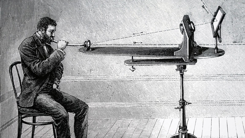
Early Optical Transmission using Bell’s Photophone. Photo: Wikipedia
The introduction of the photophone represented fairly advanced technology for its time but was not immediately recognized for its significance until much later. This was mainly attributed to the photophone’s inability to protect its transmissions from outside interference, such as cloud cover, making it impractical for widespread use.
The principles of guiding light by refraction were first demonstrated by Daniel Colladon and Jacques Babinet in Paris in the early 1840s. Later, in the 19th and early 20th centuries, light was guided through bent glass rods to illuminate body cavities for medical and dental applications.
These major advancements in the understanding of light transmission helped set the stage for the modern fiber optic cables in use today. The first working fiber-optic data transmission system was demonstrated by German physicist Manfred Börner at Telefunken Research Labs in Ulm in 1965, followed by the first patent application for fiber technology in 1966.
A confidential technology at the time, NASA first used fiber optics in the television cameras sent to the moon during their 1968 lunar mission. In the years since, fiber-optic technologies have become more affordable and commercially available, making them the ideal choice for modern-day communication systems.
Advantages/Disadvantages of Fiber Optic Cables
Even though fiber optic cable installations are more expensive than other types of cable, it is the top choice for modern communications because fiber is not susceptible to problems found in twisted-pair cable, such as near-end cross-talk (NEXT) and electromagnetic interference (EMI).
Fiber optic networks operate at very high speeds—into the gigabits—and have a large available bandwidth. Data signals can be transmitted through fiber at greater distances without the need to be refreshed or strengthened.
There is far less maintenance cost and greater data security with fiber optic installations. Optical fibers usually have a longer life cycle, lasting for over 100 years when well maintained. However, optical fiber is also very fragile and more vulnerable to bending and damage compared to copper wires.
How Fiber Optic Cables Work
Fiber optic cable functions as a “light guide,” directing the light source introduced at one end of the cable through to the other end. The light source is pulsed on and off, acting as binary code, and a light-sensitive receiver on the other end of the cable converts the pulses back into the original data.
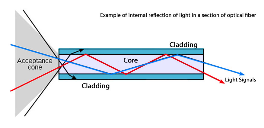
Fiber Optic Cable Light Refraction Example.
The light source used in fiber optic cable can be either a light-emitting diode (LED) or a laser. Nearly 10 billion digital bits can be transmitted per second along an optical fiber link, enough to carry tens of thousands of telephone calls.
Refinements in the construction of optical fibers, along with the development of new light source lasers and diodes, could one day allow commercial fiber-optic networks to carry trillions of bits of data per second.
Fiber Optic Cable Construction and Types
A fiber optic cable is essentially a network cable consisting of one or more strands of glass (about the thickness of human hair) encased in an insulated outer jacket. This type of cable has been designed specifically for the high-performance transfer of long-distance communications networks and contains the following components:
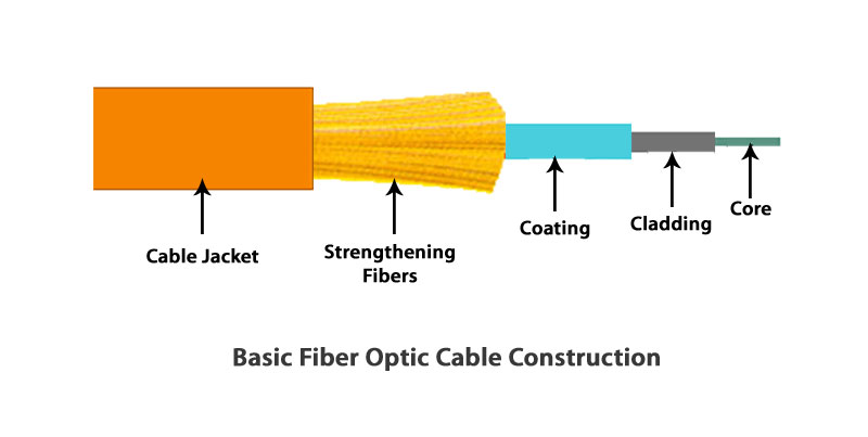
Fiber optic cable elements and basic construction.
Core
A fiber optic core is the physical medium that transports optical data signals from an attached light source to a receiving device. The core is a single continuous strand of glass or plastic that is measured in microns (µ) by the size of its outer diameter. All fiber optic cables are sized according to their core’s outer diameter. Cables with a larger core can carry more light.
Cladding
Fiber optic cladding is the thin layer that surrounds the fiber core and serves as a boundary that contains the light waves, enabling data to travel throughout the length of the fiber segment. The light travels through the core by constantly reflecting from the cladding and stays confined to the core because the cladding has a lower refractive index (a measure of its ability to bend light).
Coating
Fiber optic cables are coated with a layer of plastic that surrounds the core and cladding to reinforce and protect the fiber strands inside. Coatings are measured in microns and can range from 250 to 900 microns.
Strengthening Fibers
Extra fibers are added in fiber optic cables to help protect the core against crushing forces and excessive tension during installation. The materials used for strengthening the cable can range from Kevlar to gel-filled sleeves.
Cable Jacket
Like with all types of cable, the jacket is the outermost protective layer. Most fiber optic cables have an orange jacket, although some types can have black or yellow jackets.
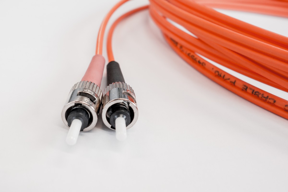
Fiber Optic Cable with Orange jacket. Photo: PxHere
Fiber Optic Design Types
Fiber optic cables can be classified by two basic designs: Loose-tube, specifically designed for harsh outdoor environments, and tight-buffered cable, mostly used for indoor applications.
Loose-tube
Loose-tube cables protect the fiber core, cladding, and coating by encasing all of the components within semi-rigid protective sleeves or tubes. In cables that hold more than one optical fiber, each individually sleeved core is bundled together loosely within a common outer jacket.
The core may be surrounded by additional materials to provide greater tensile strength, while the outer polyethylene jacket is extruded over the core. When armoring is required, a corrugated steel tape is formed around a single jacketed cable with an additional jacket extruded over the armor.
Tight-buffered
With tight-buffered cable designs, the buffering material is in direct contact with the fiber. This design provides a rugged cable structure to protect individual fibers during installation. Multi-fiber, tight-buffered cables are often used in general building and plenum applications.
Fiber Optic Operating Modes
Single-Mode fiber cable contains a single strand of glass fiber with a diameter of 8.3 to 10 microns that allows only one mode of light to propagate. Because of this, the number of light reflections created as the light passes through the core decreases, lowering attenuation and creating the ability for the signal to travel further.
Multi-mode fiber is made of multiple strands of glass fibers, with a combined diameter in the 50-to-100 micron range. Each fiber in a multi-mode cable is capable of carrying a different signal independently from those on the other fibers in the cable bundle.

Single Mode vs. Multimode Fiber Optic Cable. Photo: Wikipedia
Fiber Optic Attenuation
Signal attenuation in an optical fiber is measured in decibels (dB). Fiber optic cable specifications express loss as attenuation per 1 km length (dB/km). This value is multiplied by the total length of the optical fiber in kilometers to determine the fiber’s total loss in dB. Measuring attenuation in a fiber-optic cable is critical for obtaining the maximum performance from a system design.
Losses Inherent to Fiber Optic Cable
Fiber optic cables are susceptible to various energy losses that can be attributed to either physical impurities or problems with the installation. Loss of signal strength at the molecular level in fiber is mainly due to contaminants in the glass, such as moisture.
The ingress of water into an optical fiber is one of the main factors contributing to the fiber’s increased attenuation as it ages. Rays of light encountering these variations and impurities are scattered in many directions and lost, a condition known as Rayleigh scattering.
Laser light shining through a fiber optic cable is also subject to loss of signal strength, primarily through dispersion and scattering of the light within the cable itself. This is because the faster the laser fluctuates, the greater the risk of dispersion. Devices used to strengthen a light signal, called repeaters, may be necessary to refresh the signal in certain applications.
Fabrication Loss
The ability to join optical fibers with low loss is critical for efficient communication and is a more complex process than splicing electrical wire or power cable. Fiber splicing involves careful cleaving of the fibers, precise alignment of tiny fiber cores, and the seamless coupling of these aligned cores.
For fiber optic applications that require a permanent connection, the fusion splice is most commonly used. In this technique, an electric arc is used to melt the ends of the fibers together. Temporary or semi-permanent connections are made by means of specialized optical fiber connectors.
Inconsistencies in the fiber manufacturing process will result in the loss of light at the molecular level, which is why strict tolerances must be maintained at the factory. Something as small as a 0.1% change in the core diameter can result in a 10 dB loss per kilometer.
How to perform a fiber fusion splice
Splice Loss
Splice loss in a fiber network occurs at each splice location. Mechanical splices usually have the highest loss, commonly ranging from 0.2 to over 1.0 dB, depending on the type of splice. Fusion splices have lower losses, usually less than 0.1 dB.
A loss of 0.05 dB or less is usually achieved with good equipment and experienced personnel. High loss can be attributed to a number of factors, such as poor cleave, misaligned fiber cores, or core diameter mismatch.
Connector Loss
Losses at fiber optic connectors commonly range from 0.25 to over 1.5 dB and depend greatly on the type of connector used. Other factors that contribute to the connection loss include dirt or contaminants on the connector, improper installation, damaged components, poor cleave, and misaligned fiber cores.
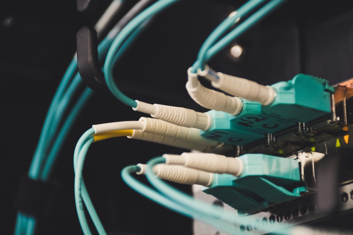
Fiber Optic Cable Network. Photo: PxHere
Bend Loss
Bend loss occurs at bends in an optical fiber that exceed the cable’s rated bend radius. Fiber optic cables are very fragile, and it doesn’t take much force to break the glass inside. Bend loss can also occur on a smaller scale from buffer or jacket imperfections and poor installation practice.
Testing Fiber Optic Cable
Fiber optic installations are responsible for delivering critical data and require great care to ensure they are kept clean and functioning efficiently. Several measurements can be taken on fiber optic cables to determine their integrity both during installation and well after being placed into service.
Periodic visual and mechanical inspections are recommended to ensure that the fiber cable and its connections have not been subjected to physical or mechanical damage. Optical tests are used on the cable to ensure losses are kept to a minimum.
Basic fiber optic testers function by shining a light down one end of the cable, with a receiver calibrated to the strength of the light source at the other end. With this type of equipment, you can measure how much light is going down the length of the cable.
Most test equipment will produce the results in decibels (dB) lost, which you then compare to local site specifications or manufacturer’s recommendations. Time-domain reflectometry (TDR) transmits high-frequency pulses onto a cable so you can examine the reflections along the cable and isolate faults.
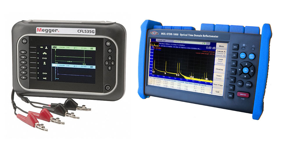
Both Electronic and Optical Time-Domain Reflectometers operate on a principle similar to radar. An electronic TDR is used for power cable and the optical TDR is for fiber.
Attenuation loss (or decibel loss) is measured in dB/km. This is the decrease of signal strength as it travels through the fiber optic cable.
Return loss is the amount of light reflected from the far end of the cable back to the source. The lower the number, the better. For example, a reading of -50 dB is better than -10 dB.
Graded refractive index measures how much light is sent down the fiber. This is commonly measured at wavelengths of 850 and 1300 nanometers.
Propagation delay is the time it takes a fiber optic signal to travel from one point to another over a transmission channel.