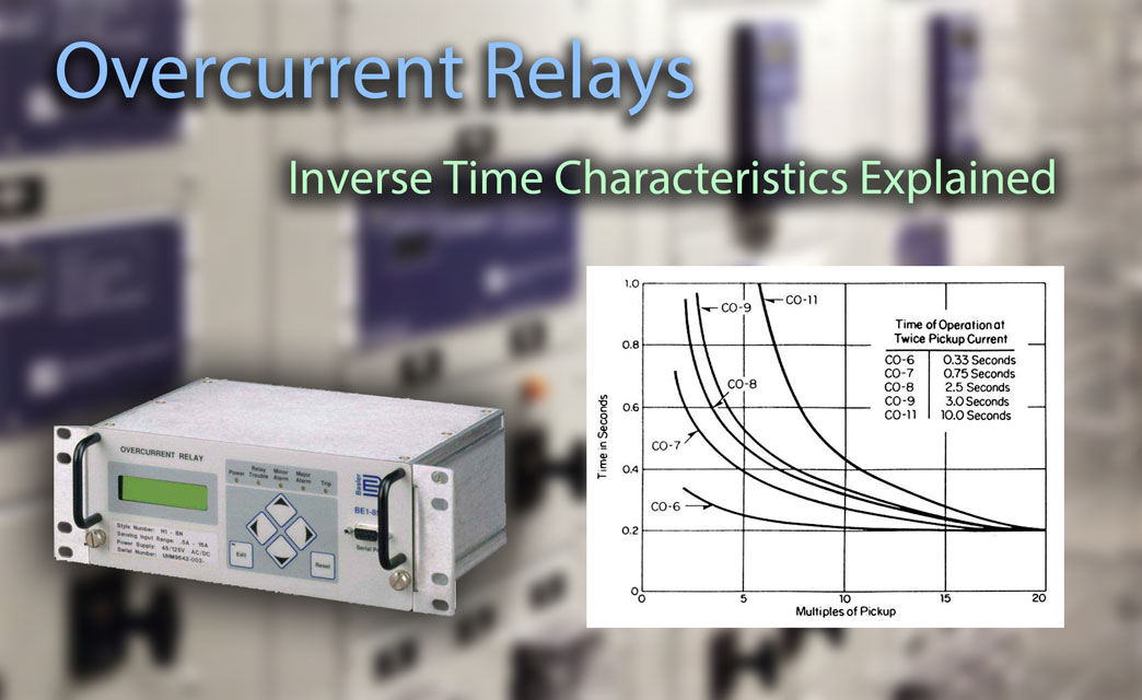
Overcurrent relaying is one of the simplest and most economical types of protection employed for power system feeders, transformers, generators, and motors. From the era of basic electromechanical elements to the contemporary use of advanced microprocessor applications in modern relays, overcurrent protection has been at the core of power systems for centuries.
The characteristics of overcurrent relays are based on operating times typically governed by a time vs. current curve. There are three main types of overcurrent relay: (1) Instantaneous, (2) Time-Dependent (Definite time or inverse), and (3) Mixed (Definite time and Inverse).
1. Instantaneous relays have operating times usually less than 3 cycles. These relays operate without an intentional time delay, hence they are referred to as instantaneous units. The pickup current is adjustable, and the application engineer can choose various settings from a wide range.
2. Time-dependent relays, as the name implies, operate with an intentional time delay. The pick-up current (minimum current at which the relay operates) and the time before trip are both adjustable.
There are a total of five types of time dependent relay, broken into two categories: Definite-Time and Inverse-Time.
A. Definite-time relays operate with an intentional time delay that is adjustable along with the current pick-up level. Although these relays are adjustable, their time delays are not necessarily dependent on the current value.
B. Inverse-time relays have an operating time depending on the magnitude of the current, generally with an inverse characteristic (the operation time of the relay is smaller as the current gets larger). These relays also have two settings: the pick-up current and the curve type.
In electromechanical relays, the curve is set by means of a dial, which is why the setting is referred to as the “time dial setting” or TDS. In some relays, a Time Dial Multiplier is used instead of the Time Dial setting, but their functions are similar.
TOC & IDMT
Inverse Time Over Current is also referred to as Time Over Current (TOC) or Inverse Definite Minimum Time (IDMT), indicating that the trip time of the relay is inversely proportional to the applied fault current.
Overcurrent Relay Time Delay Curve Types
The trip time of an inverse curve is calculated from the following parameters:
- Trip curve: Selected from the standard set of IEC and IEEE curves.
- Relay pickup current (A): The electrical current pickup set point Is in the relay.
- Fault current (A): The expected short circuit fault current I.
- TMS or TD setting: IEC time multiplier setting (TMS). IEEE time dial (TD).
Degrees of Overcurrent Inverse Curves
The time it takes for the relay to trip will vary depending on the curve slope. These curves can be used by engineers to coordinate with other protective devices upstream for selectivity and backup.
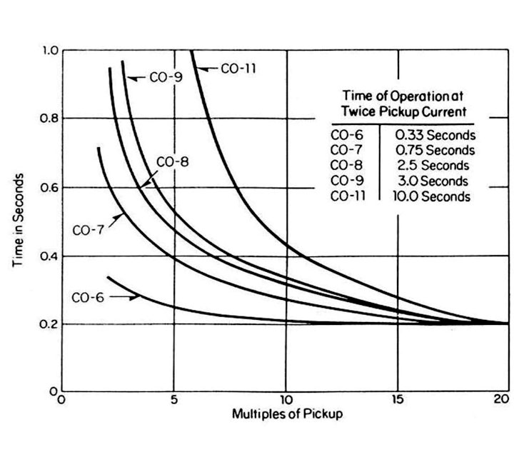
Degrees of Overcurrent Inverse Curves (ABB Relays)
Their time-current characteristic curves are:
- Definite minimum (ABB CO-6)
- Moderately inverse (ABB CO-7)
- Inverse (ABB CO-8)
- Very inverse (ABB CO-9)
- Extremely inverse (ABB CO-11)
When plotted on a chart, the different characteristics between each curve become apparent. The more inverse the curve shape, the greater difference in trip times.
Electromechanical overcurrent relays are often constructed to a specific curve shape, such as the ABB CO-6, CO-7, CO-8, etc. Changing the electromechanical curve shape means replacing the entire unit, which can be very expensive and results in surplus equipment.
Modern digital relays are programmable, allowing curve shapes to be easily changed without the need for replacement.
How Inverse Time Curves are Calculated
Each standardized relay protection curve will have its trip time calculated from either IEEE C37.112 or IEC 60255 equations.
IEEE C37.112-1996 Equation for Trip Time
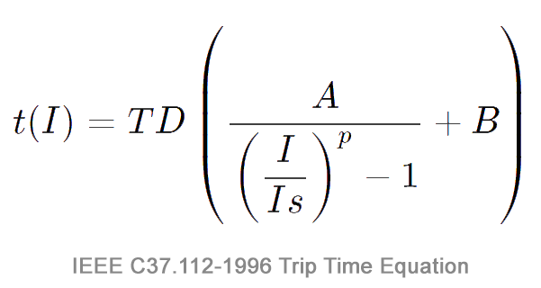
IEEE C37.112-1996 Equation for Trip Time
- A = Time factor for over-current trip
- I = Actual Current
- Is = Relay Pickup Setting
- p = Exponent for inverse-time
- B = Timer coefficient for over-current trip
Note: IEEE C37.112-1996 does not specify coefficients in its standard curve equation, and therefore, each manufacturer’s curve is similar. A TDM (Time Dial Multiplier) is sometimes used instead of TD (Time Dial). The relationship is: TDM = TD / 7.
| Curve Type | A | B | p |
|---|---|---|---|
| Moderately inverse | 0.0515 | 0.114 | 0.02 |
| Very inverse | 19.61 | 0.491 | 2.0 |
| Extremely inverse | 28.2 | 0.1217 | 2.0 |
IEC 60255 Equation for Trip Time
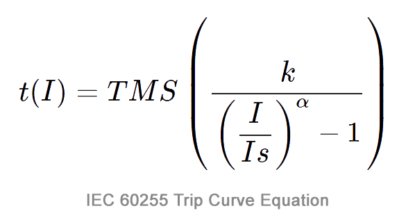
IEC 60255 Equation for Trip Time
- Is is the current setting.
- I is the actual current.
- k and α are the curve type constants.
| Curve type | k | α |
|---|---|---|
| Standard inverse | 0.140 | 0.020 |
| Very inverse | 13.5 | 1 |
| Extremely inverse | 80 | 2 |
| Long time standard inverse | 120 | 1 |
Examples
A. Calculate the tripping time for a relay set at 1000A pickup current and TMS setting of 1 (IEEE Very Inverse) with 10kA of fault current.
- 10000 / 1000 = 10
- 10^2 = 100
- 100-1 = 99
- 19.61 / 99 = 0.198
- 0.491 + 0.198 = 0.689
0.689 Seconds
B. Calculate the tripping time for a relay set at 1000A pickup current and TMS setting of 1 (IEC Very Inverse) with 10kA of fault current.
- 10000 / 1000 = 10
- 10^1 = 10
- 100-1 = 9
- 13.5 / 9 = 1.5
1.5 Seconds
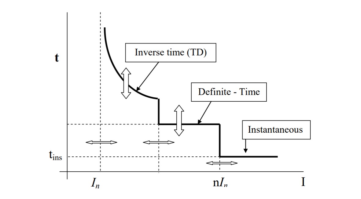
Mixed Curves (Definite time and Inverse) Overcurrent Relays
Thanks to the advent of the digital relay, its possible to have all of the advantages that come with the different types of relay elements packed into a single programmable unit.
Nearly any combination of instantaneous, definite-time, and inverse-time elements may be used. The most common type of mixed relay is the inverse definite with minimum time lag relay (IDMT) which combines inverse characteristic plus definite time characteristics.
Related: Protective Relay Testing and Maintenance Overview
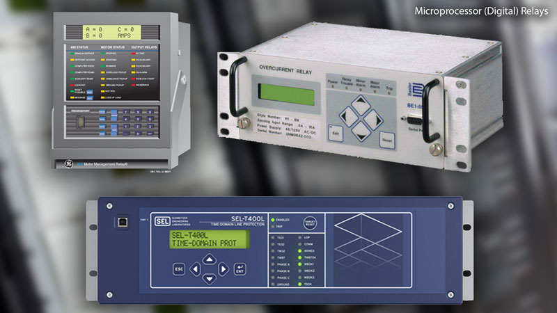
Microprocessor-Based (Digital) Relays. Photo: TestGuy.