What is an acceptable contact resistance reading?
Low-Resistance ohmmeters are frequently used by electrical test technicians technicians to obtain high-precision resistance measurements (below 1 ohm) from various types of apparatus like circuit breaker and switch contacts, cable and busway connections, transformers and machine windings, and fuses.
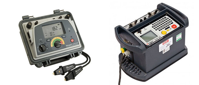
10A DLRO (left) and 100A DLRO (right). Photo: Megger
There are several factors that can affect connection resistance values, such as the type of equipment, conductor material, and conductor surface temperature. For example, low resistance measurements taken from a hot motor during routine maintenance will differ greatly from those taken at the time of installation.
Test equipment operators should have a good understanding of what value is acceptable for a given piece of equipment based on available manufacturers’ data and industry standards. Comparisons can also be made with data collected from similar equipment operating in similar environments.
Recommended: Test Equipment 101: The Basics of Electrical Testing
Because electrical connections have a tendency to degrade slowly over time, low resistance readings should be tracked over time to develop a clear trend. The following tips can help technicians better predict when a component is at the greatest risk of failure:
Manufacturer standards
Equipment manufacturers will occasionally recommend low-resistance values in their literature but not always. The universal rule of thumb for contact resistance has often been to get the reading as low and even as possible between each phase. The higher the frame size, the lower the contact resistance readings should be.
Contacts (50%)
For circuit breakers, switches, and similar equipment with moving contacts, NETA Electrical Testing Standards define a minimum deviation of 50% between phases. In this case, simply multiply the lowest value by 1.5 and this will determine the maximum limit for other phases.
Example: A low value of 20 microhms would allow for a limit of 30 microhms (20 x 1.5).
Fuses (15%)
Fuse resistance has a much tighter tolerance of 15% between phases, in accordance with NETA standards. The calculation is made in the same manner as contacts, with the only difference being a multiplier of 1.15 rather than 1.5 as used with contacts.
Example: A fuse resistance of 1000 microhms would allow for a max limit of 1150 microhms for the other fuses. In the case of a fused switch, the contacts are evaluated on 50% while the fuses would be evaluated on 15%.
Batteries (20%)
IEEE 450-2010 Section 5.3.1 specifies that the variation of intercell connection resistance between batteries cannot be more than 20% above the installation value or ceiling value set by the system designer. NETA MTS-2019 standards specify 50% between similar intercell connections in Section 7.18.
Lowest Value is Key
Resistance measurements are based on the lowest value obtained. When DLRO testing in the real world, the lowest value you encounter may be the last measurement you take. If you measure a new low value, the maximum limit must be adjusted for the new low.
Importance of Test Current
The output current of the test equipment being used and temperature of the test specimen will have a big effect on the measured value. A general rule of thumb for contact-resistance testing is to use the highest current possible without exceeding the current rating of the device under test.
The most common portable low-resistance ohmmeters carried by technicians are limited to 10A. When testing with higher currents, care must be taken not to heat the sample to a point that would cause a change in value.
References
- Guide to Low Resistance Testing - Megger
- Critical Maintenance for Circuit Breakers - Jim White, NETA World Summer 2007
- NETA Acceptance/Maintenance Specifications

