
Electrical testing has long been a fundamental practice for assessing the functionality and safety of electrical equipment. Traditional methods often involve applying a steady voltage or current signal and measuring a straightforward response, such as resistance, continuity, or insulation quality.
However, with advancements in computer technology and analytical tools, modern electrical testing methods have become far more sophisticated. These approaches incorporate multiple measurements taken over time, varying test parameters, and advanced data analysis techniques. The result is a more comprehensive understanding of an apparatus’s condition, enabling better diagnostics and predictive maintenance.
This article explores several advanced electrical testing techniques and highlights the modern test equipment that allows technicians to perform accurate and rapid analysis in the field.
1. Insulation Resistance Profile (IRP)
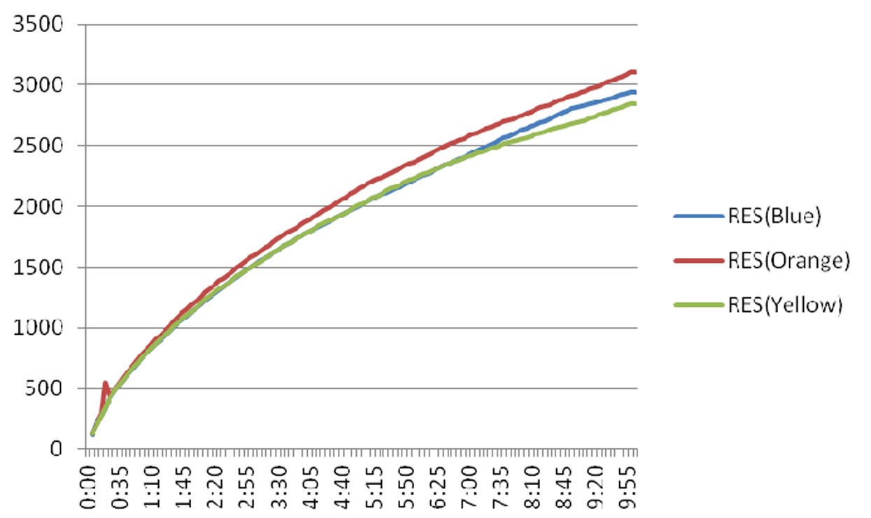
Insulation Resistance Profile plots the insulation resistance of an apparatus over time. Photo: MotoDoc LLC
An Insulation Resistance Profile (IRP) provides a detailed graphical representation of an insulation system’s resistance over time. This profile is created by taking resistance measurements at regular intervals, such as every 5 seconds, over a specified duration, typically 10 minutes.
The resulting data can help identify the condition of the insulation system, which generally falls into one of four distinct profiles:
- Normal: Indicates healthy insulation with no significant issues.
- Moisture: Suggests the presence of moisture within the insulation material.
- Contamination: Points to impurities or foreign materials affecting insulation performance.
- Embrittlement: Reflects aging or degradation that makes the insulation brittle and less effective.
Additionally, when the insulation resistance exceeds 5000 megohms, the IRP may reveal subtle characteristics that could otherwise go unnoticed, offering further insights into the insulation’s condition.
2. Sweep Frequency Response Analysis (SFRA)
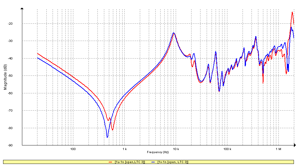
SFRA gives a detailed look at how a transformer responds at different frequency ranges. Photo: Indiamart.
Sweep Frequency Response Analysis (SFRA) is an advanced diagnostic method used to evaluate the mechanical and electrical integrity of equipment containing windings, such as transformers and reactors. The technique involves sending a signal across a range of frequencies into the windings and measuring the response signal that returns.
The results are then analyzed by comparing them to a reference, such as a baseline test performed when the equipment was new, or to results from previous tests. This comparison helps detect potential issues, such as mechanical damage, physical deformation, or electrical changes within the windings.
SFRA is a versatile tool used in various scenarios, including:
- Baseline Testing: Establishing a reference for new transformers.
- Routine Diagnostics: Monitoring equipment condition during regular maintenance.
- Post-Fault Testing: Assessing potential damage following a system fault or incident.
By identifying subtle changes, SFRA allows for early detection of problems, reducing the risk of unexpected equipment failures.
Related: SFRA Insights: Understanding Low, Mid, and High Frequencies
3. Dielectric Frequency Response (DFR)
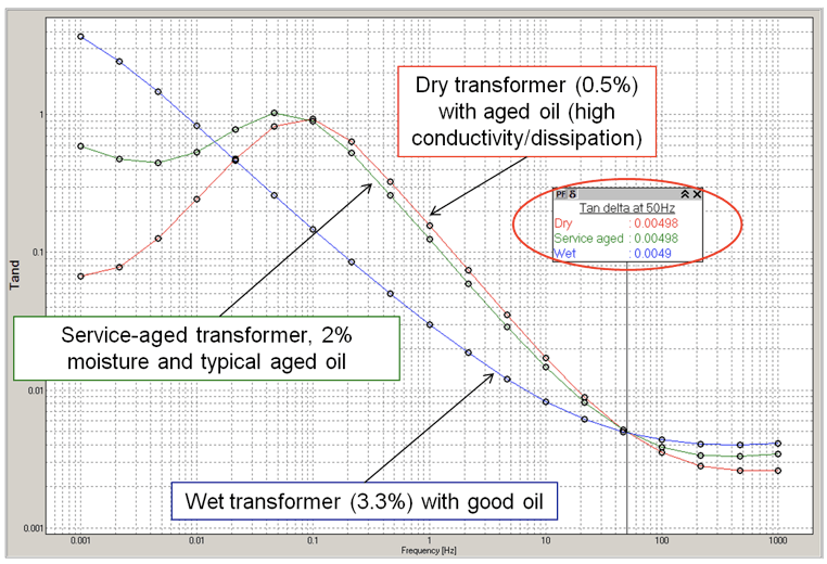
Dielectric Frequency Response is used to measure dielectric losses and capacitance. Photo: INMR.
Dielectric Frequency Response (DFR), also known as Frequency Domain Spectroscopy (FDS), is a non-destructive diagnostic method used to assess the condition of insulation in electrical equipment such as power transformers and cables. This technique measures a material’s dielectric losses and capacitance across a wide range of frequencies.
DFR is particularly effective for evaluating insulation health and estimating moisture content within the system. The process involves measuring the dielectric response of the material and comparing it to a theoretical model to determine critical parameters such as moisture content and oil conductivity.
The results of DFR testing are typically presented as curves that plot:
- Capacitance
- Dissipation Factor (Tan δ)
- Power Factor
These values are charted against frequency, providing a clear view of how the insulation performs under different electrical conditions. DFR enables technicians to identify moisture, aging, or contamination within insulation systems, allowing for accurate diagnostics and timely maintenance decisions.
4. Electromagnetic Signature Analysis (EMSA)
Electromagnetic Signature Analysis (EMSA) is a diagnostic technique that shares similarities with power quality analysis but utilizes a unique data collection approach. Instead of connecting to each energized phase conductor, EMSA uses a single split-core Radio Frequency Current Transformer (RFCT) placed around a power conduit, ground, or neutral lead of the equipment under test.
This method captures radio frequency signals emitted by the electrical apparatus. These signals form an EMSA signature, which is distinctive to each physical location and defect within the system. Importantly, no direct connection to the equipment is required; all data is collected through electromagnetic coupling.
EMSA signatures contain patterns specific to various anomalies, characterized by differences in frequency and amplitude. These patterns can include phenomena such as:
- Corona Discharge
- Arcing
- Radio Signals
- Random Noise
- Electronic Transients
The collected data is analyzed using computers, which may involve human engineers or autonomous interpretation through machine learning algorithms. This allows for precise identification of issues based on the unique EMSA signature.
Data collection adheres to the international standard CISPR 16, which governs the measurement of radio disturbance voltages and currents in the frequency range of 9 kHz to 1 GHz. This ensures consistency and accuracy in the diagnostic process.
5. Magnetron Atmospheric Condition (MAC) Test

The vacuum interrupter leak-rate test (MAC test) is based on the Penning Discharge Principle. Photo: Vacuum Interrupters, Inc.
Vacuum interrupters are traditionally tested in the field using the high-potential (hi-pot) test, which evaluates their dielectric strength. In this method, a high voltage is applied across the open contacts, and any resulting leakage current is measured.
While effective at identifying immediate failures, the hi-pot test provides only a simple pass/fail result and cannot detect whether the vacuum’s internal gas pressure has dropped to a critical level, which could signal future failure.
In contrast, the Magnetron Atmospheric Condition (MAC) test offers a more advanced and predictive approach for assessing vacuum interrupters. This method measures the leak rate of the vacuum, providing valuable insights into its condition before failure occurs.
Historically, the MAC test was impractical for field use due to the need for large, complex equipment to generate the required magnetic fields. However, modern technological advances have transformed this process. Portable magnetrons and condition-based maintenance algorithms now make it possible to perform vacuum leak-rate testing in the field.
The data generated by the MAC test is quantifiable and can be integrated into a predictive maintenance program. This enables technicians to monitor the health of vacuum interrupters over time, identify potential issues early, and plan maintenance or replacements proactively.
Further Reading: Magnetron Atmospheric Condition (MAC) Testing Principles
6. Continuous Liquid and Gas Monitoring (DGA)
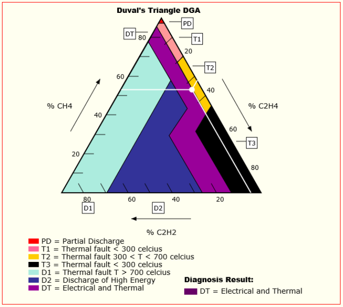
DGA can be used to categorize transformer faults, based on the relative amounts of methane, acetylene and ethylene. Photo: Github.
Continuous liquid and gas monitoring systems provide real-time insights into the health of power transformers by analyzing dissolved gases within their insulating oil. This technique, commonly referred to as Dissolved Gas Analysis (DGA), is a critical tool for proactive transformer maintenance.
The system continuously measures the concentration of key gases dissolved in the oil, such as:
- Hydrogen
- Methane
- Ethane
- Ethylene
- Acetylene
- Carbon Monoxide
- Carbon Dioxide
Abnormal levels of these gases can indicate potential issues, including:
- Overheating
- Arcing
- Partial Discharge
By detecting gas level changes early, DGA enables operators to identify and address problems before they escalate into significant failures. This early fault detection allows for timely interventions, reducing the risk of unexpected downtime and extending the transformer’s operational life.
Continuous DGA monitoring is regarded as a cornerstone of transformer health assessment and a vital part of predictive maintenance programs in modern power systems.
7. Bushing Monitoring
Online bushing monitoring systems provide real-time data on the condition of bushings, regardless of weather conditions, load levels, or voltage fluctuations, with the same sensitivity as traditional offline measurements.
While offline bushing tests are typically conducted on a routine schedule—often once every few years—many failure mechanisms in bushings can develop quickly, sometimes within a matter of days or weeks. Furthermore, some failures are dependent on temperature and voltage changes, which are difficult to replicate during offline testing.
Online bushing monitoring addresses these limitations by continuously tracking bushing performance in real-world conditions. This provides more accurate and timely insights into potential issues, helping to enhance the overall performance and reliability of transformers. By identifying early signs of failure, online monitoring enables operators to take preventive actions before expensive or disruptive failures occur.
8. Online Partial Discharge (PD)
Online partial discharge (PD) testing is a non-destructive, non-intrusive method used to assess the condition of electrical insulation. This technique helps identify potential issues such as dielectric irregularities or weak spots in the insulation, which could lead to future failures.
Online PD testing offers several key benefits:
- Continuous Monitoring of Cables: Tracks insulation health over time.
- Locating Problematic Joints and Terminations: Identifies weak points that may cause insulation breakdown.
- Prioritizing Cable Replacements: Helps decide which cables need replacement based on their condition.
- Ensuring Quality of Installed Cables: Verifies the integrity of cables after installation.
By monitoring partial discharge online, system operators gain continuous insight into the insulation’s condition while the electrical equipment remains in service. This real-time data helps detect developing issues under normal operating conditions, enabling timely maintenance and preventing unexpected failures.
9. Vibration Analysis
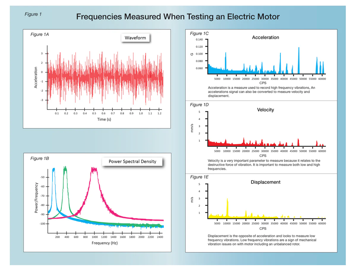
Motor vibration analysis frequencies measured. Photo LEI Corp.
Vibration analysis of electrical motors is a diagnostic process that measures and analyzes the vibration levels and frequencies of a motor to evaluate its health. This technique is important for identifying potential issues that could affect the motor’s performance, lifespan, or efficiency. Vibration analysis is widely used in industries such as aerospace, manufacturing, and automotive due to its effectiveness and reliability.
Vibration analysis can be used for several purposes:
- Finding and Repairing Developing Problems: Identifies early signs of wear or damage before they become critical.
- Detecting and Monitoring Chronic Problems: Tracks recurring issues to manage long-term maintenance needs.
- Establishing Acceptance Criteria for Testing: Sets benchmarks for motor performance during acceptance testing.
- Predicting Failures: Forms part of a predictive maintenance strategy, allowing for proactive repairs.
To perform vibration analysis, an accelerometer is attached to the motor. This device generates a voltage signal that corresponds to the level and frequency of the motor’s vibration, providing valuable data for diagnosing potential problems.
10. Infrared Thermography (IR)
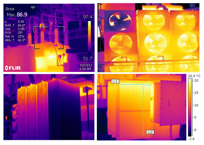
Infrared thermography is an invaluable tool for detecting early signs of potential issues within electrical systems. Unlike traditional maintenance methods, infrared inspections can identify problems before any physical evidence of failure appears, allowing for proactive intervention.
One of the main advantages of infrared thermography is that it is a non-contact method. The inspection process involves scanning electrical equipment quickly and efficiently, even while it remains in service. Since no direct contact is required, infrared thermography minimizes operational disruption and allows for comprehensive assessments with minimal downtime.
During infrared inspections, common electrical issues that can be identified include:
- Loose Connections
- Overloaded Circuits
- Unbalanced Loads
- Faulty Equipment
Even if an abnormal thermal image does not immediately suggest a clear problem, it serves as a valuable signal, prompting further investigation to prevent future failures. Infrared thermography helps ensure equipment operates reliably, extending its lifespan and preventing costly disruptions.
Recommended: Infrared Thermography for Electrical Distribution Systems
Conclusion
Advanced electrical testing methods have revolutionized the way we monitor and maintain electrical equipment, offering more precise and predictive insights into system health. Techniques such as Insulation Resistance Profiling, Sweep Frequency Response Analysis, and Dielectric Frequency Response provide valuable data on insulation condition, while methods like Sweep Frequency Response Analysis and Electromagnetic Signature Analysis help detect issues in equipment such as transformers and reactors.
Additionally, advancements in online monitoring—such as continuous gas and liquid monitoring, bushing monitoring, and partial discharge detection—enable real-time diagnostics that allow for timely maintenance and failure prevention. Tools like vibration analysis and infrared thermography further enhance the ability to detect mechanical and thermal issues early, ultimately contributing to longer equipment life and improved operational reliability.
By integrating these advanced testing methods into routine maintenance practices, operators can ensure that their electrical systems remain safe, efficient, and reliable.