Capacitors have several uses in electrical and electronic circuits. They can be used to filter out unwanted noise from a signal, to block DC voltage while allowing AC voltage to pass through, to smooth out voltage fluctuations, to provide a voltage source in a timing circuit, to store energy in power electronics, and to improve the power factor of a circuit.
The capacitor acts as a reactive element and stores energy in an electric field. Capacitive reactance controls the rate at which the capacitor charges and discharges, which helps to regulate the flow of current in the circuit.
Capacitive reactance opposes the flow of current in a circuit and its value depends on the frequency of the applied voltage and the capacitance rating of the capacitor. The reactance is calculated to determine the impedance of a circuit, which is a measure of the total opposition to the flow of current in the circuit.
Step 1: Find the total capacitance of the circuit
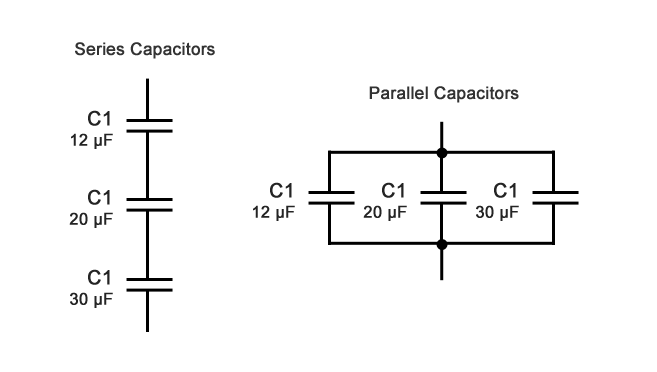
Assume we have three capacitors, a 12 µF, a 20 µF, and a 30 µF connected to a 60Hz source. What is the total capacitive reactance (XC) when connected in series or connected in parallel?

1A. For Series Capacitors
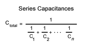
When capacitors are connected in series, the total capacitance is less than any one of the series capacitors’ individual capacitances. If two or more capacitors are connected in series, the overall effect is that of a single (equivalent) capacitor having the sum total of the plate spacing of the individual capacitors.

Series Capacitors Example
1 / 12 = 0.083, 1 / 20 = 0.050, 1 / 30 = 0.033
0.083 + 0.050 + 0.033 = 0.166
1 / 0.163 = 6.02 µF
Note: math is simplified for illustration purposes. Use a calculator for more accurate numbers.
1B. For Parallel Capacitors
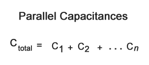
When capacitors are connected in parallel, the total capacitance is the sum of the individual capacitors’ capacitances. If two or more capacitors are connected in parallel, the overall effect is that of a single equivalent capacitor having the sum total of the plate areas of the individual capacitors.

Parallel Capacitors Example
12 + 20 + 30 = 62 µF
Step 2: Find the Capacitive Reactance
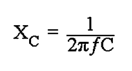
Like resistance, reactance is measured in Ohm’s but is given the symbol X to distinguish it from a purely resistive R value and as the component in question is a capacitor, the reactance of a capacitor is called Capacitive Reactance, ( XC ) which is measured in Ohms.
Since capacitors charge and discharge in proportion to the rate of voltage change across them, the faster the voltage changes the more current will flow. Likewise, the slower the voltage changes the less current will flow. This means then that the reactance of an AC capacitor is “inversely proportional” to the frequency of the supply.

XC is the Capacitive Reactance in Ohms, f is the frequency in Hertz and C is the AC capacitance in Farads. It’s very important to convert our example from microfarads to farads in order to get a correct result!
1 µF = 0.000001 F
60Hz Series Example
6.02 µF = 0.000006 F (simplified)
2 x 3.14 x 60 x 0.000006 = 0.0022608
1 / 0.0022608 = 442.32 Ohms
60Hz Parallel Example
62 µF = 0.000062 F
2 x 3.14 x 60 x 0.000062 = 0.0233616
1 / 0.0233616 = 42.805 Ohms
Now let’s see what happens when the frequency is changed to 400 Hz:
400Hz Series Example
2 x 3.14 x 400 x 0.000006 = 0.015072
1 / 0.015072 = 66.34 Ohms
400Hz Parallel Example
2 x 3.14 x 400 x 0.000062 = 0.155744
1 / 0.155744 = 6.42 Ohms
