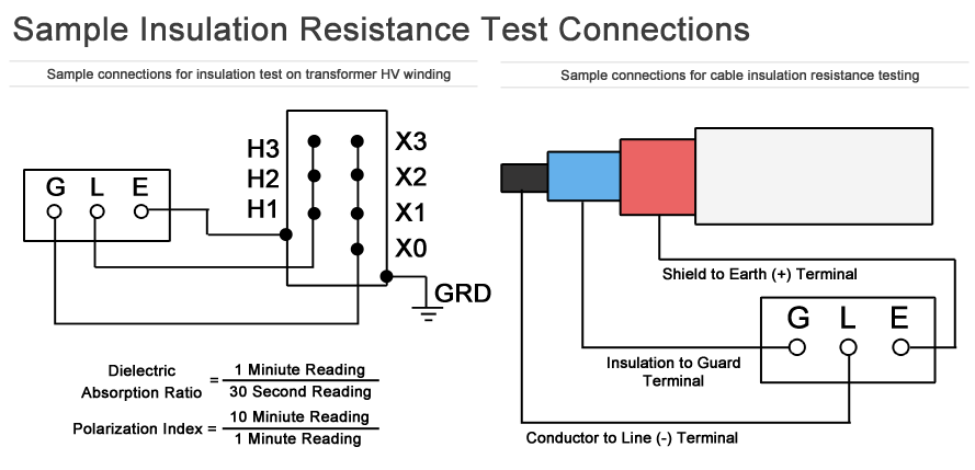
Conducting periodic insulation resistance tests can help prevent hazards such as electric shock and short-circuits caused by deteriorating insulation within electrical power distribution equipment. Testing can also be a quick and convenient way to gather important information regarding the health and quality of electrical insulation.
1. Test Connections
Insulation resistance testing is a simple overpotential test that measures leakage current between two conductors or other potential (such as a ground). For poly-phase circuits, several combinations of connections are made between line, phase, and ground.
Examples of test connections for insulation resistance include: phase-to-neutral, phase-to-ground, and phase-to-phase. Care must be taken when applying voltage, always ensure all points of the test circuit are properly marked and isolated from bystanders.
2. Test Voltage
500 volts is generally accepted as a safe voltage for simple electrical wiring checks in most commercial buildings. Troubleshooting of distribution equipment may require a test voltage of 1kV to help exploit and identify weak spots in the insulation.
Sensitive applications like data/telecom wiring should use a very low voltage, such as 50V. Several standards exist to provide recommended insulation resistance test voltage, including those from IEEE, NFPA, and NETA.
3. Test Duration
When conducting an insulation resistance test, the applied voltage must work to adequately charge the circuit under test. The resulting currents will cause the tester to display readings that vary at first, and then stabilize. Its generally accepted that one minute is acceptable but pass/fail testing can be completed in less time.
4. Acceptable Values
What is considered acceptable insulation resistance depends on several factors but most subject matter experts agree that anything in the Megohm range is typically safe to energize. NETA standards specify a minimum acceptable value of 100 Megohms for most low voltage distribution apparatus other than transformers.
5. Effects on Readings
Insulation temperature is the biggest factor when interpreting insulation resistance measurements. All recorded results should be corrected to a common base temperature, such as 20C.
When trending values over time, temperature corrected readings should be used to provide greater accuracy. A continued downward trend is an indication of insulation deterioration even though the resistance values measured is above the minimum acceptable limit.
Humidity is another factor that can have an effect on insulation resistance readings. Each type of insulating material will react differently and results can be drastically reduced in environments with high relative humidity. For this reason, it is important to document the ambient temperature and humidity on the test report.
6. Ratios (DAR and PI)
Single insulation resistance readings do not offer much value about the health of an insulation system aside from revealing gross anomalies. In order to obtain a true measure of how well electrical insulation can perform under stress, tests are made over a set time period and the values are divided to obtain a ratio. Values for DAR and PI can be compared to tables formulated by IEEE which indicate the expected insulation condition.
The Dielectric Absorption Ratio (DAR) is the ratio of the insulation resistance value measured at 1 minute divided by the value measured at 30 seconds. Values less than 1.25 indicate a questionable insulation condition, 1.25 to 1.60 is considered “good insulation,” and anything above 1.60 is classified as excellent.
The Polarization Index (PI) is the ratio of the insulation resistance value measured at 10 minute divided by the value measured at 1 minute. Any PI value below 1.0 is considered bad insulation because the measured resistance was eventually less than when the test started. Measured values ranging anywhere between 1.0 and 2.0 is questionable insulation, 2.0 to 4.0 is classified as good, and anything above 4.0 is considered excellent.
For electric motors, IEEE specifies two recommended minimum PI values based on thermal class rating. Class A has a minimum PI of 1.5 while all others are specified at 2. When the PI value exceeds 8 it may indicate insulation that is dried out and brittle to the point that it could fail mechanically as well as electrically.
IEEE Standard 43 Section 12.2.2 recommends that when the insulation resistance is above 5 Gigaohms that the PI is not valid. This is because the leakage current is in the microampere range and too many factors can influence the measurement.
7. Safety
Insulation resistance testing is generally safe for most electrical apparatus but care must be taken when testing equipment with solid state components. Circuit breakers with electronic trip units may require special steps be taken before insulation testing can proceed.
Power is extremely limited on an insulation resistance tester but operators can be subjected to electric shock if the proper safety procedures are not followed. Large capacitive items such as windings and long runs of cable are capable of storing lethal capacitive charges. A quality insulation tester will be capable of safely discharging a circuit after testing.
It’s recommended that equipment under test be grounded for a period of 4 times the length of the test period to safely dissipate any stray capacitive charges. If ample time is not allowed for discharge, stored energy can rebuild. Shorting a piece of equipment directly to ground immediate following a test may also damage the insulation. For this reason, a properly rated discharge stick with a resistor should be used.

