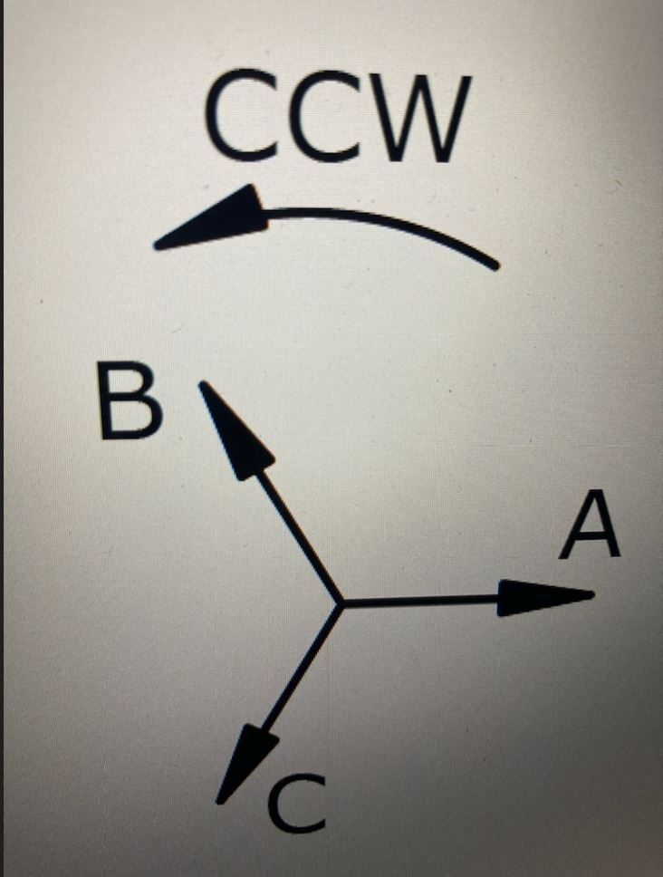
An engineer tells me that this phasor image that is shown on a drawing set for a system we interconnect to depicts an A-B-C sequence. I thought it was A-C-B. Where is the misunderstanding? Is there some convention where some engineers think the phasor arrows rotate in the graphic, while others think the rotation arrow actually rotates around the phasor arrows? I thought I understood this topic as an electrician.
1 Like
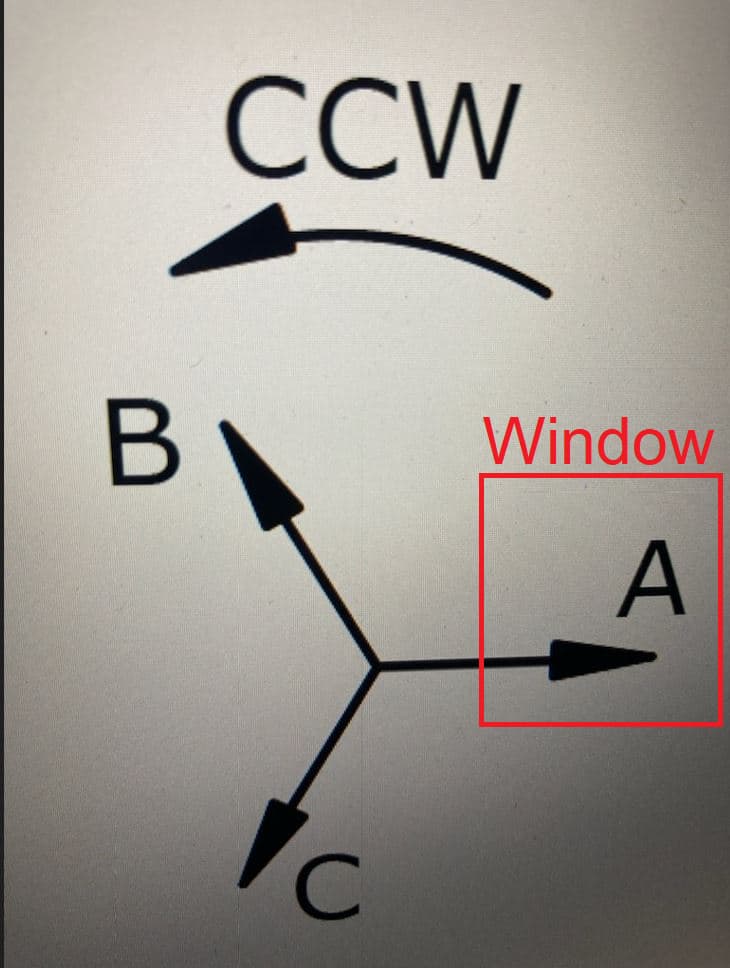
The way I was taught was imagine you are looking through a window. In counterclockwise rotation, the phases would pass through the window A-C-B.
I’ve been an engineer in the power industry for 40 years (BSEE, MSEE). In the diagram, the CCW rotation is the convention. According to this phasor diagram, the rotation is ACB. If you write this sequence out several times (ACBACBACB) and look at the sequence, you do not find any three letters that indicate ABC. If you swap any two phasors and write out the sequence, you will see an ABC sequence.
1 Like