This guide covers the basic theory and applications of power quality monitoring and analysis. Photo: TestGuy.
There are several ways in which electric power can be of poor quality. Improper wiring, incorrect grounding, and unbalanced loads are just a few examples of conditions that can produce electrical noise through a system and compromise power quality.
There is no such thing as perfect power quality in the real world. Service interruptions, equipment malfunctions, and excess power consumption are all common symptoms of poor power quality.
To minimize the risk of lost production and damage to electrical equipment, power quality analysis is employed to monitor a system for problems, identify the cause, and initiate corrective action. After collecting system data in the field, a power quality engineer will search for unusual events and determine the appropriate power conditioning equipment or other steps needed to resolve the issue.
Contents
- Ideal Power Conditions
- Power Interruptions
- Undervoltage, Overvoltage, Sags, Swells
- Flicker, Transients and Noise
- Power Factor, Unbalance and Harmonics
- How Power Quality is Measured
- Power Quality Reports
- Techniques for Improving Power Quality
- Power Quality Standards
- Further Reading
Ideal Power Conditions
It is important that power serving electrical loads is “clean,” meaning voltage and current waveforms are relatively in phase, free of distortion, and balanced between each other. Low-quality power can increase utility bills and cause damage to critical power equipment, resulting in higher production costs and a greater chance of downtime.
An “ideal” three-phase power system has the following characteristics:
- The current is in phase with the voltage for each phase. Power Factor = 1.
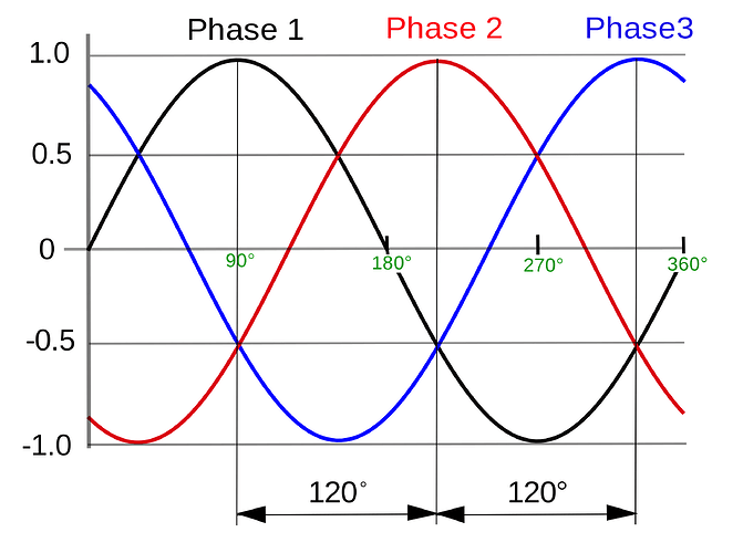
- The phase voltage and currents are exactly 120 degrees apart and all equal to each other. No unbalance.
- The voltage and current sine waves are not distorted or interrupted in any way.
- The source impedance is zero, so that events at the load don’t affect the source voltage.
- The actual frequency is equal to the nominal frequency.
In an ideal 3-phase system, voltage and current waveforms are relatively in phase, free of distortion, and balanced between each other. Photo: Wikimedia.
No power system is “ideal” in the real world, but understanding these characteristics can help identify non-ideal power features of real systems. There is some acceptable range of deviation from the “ideal” for each application, which can be defined as “acceptable power.”
In the United States, acceptable limits for service voltage and utilization voltage are defined in ANSI C84.1. Power quality monitoring is employed to ensure that an electrical power system is operating within acceptable limits and to capture waveform distortion and other anomalies that may cause power interruptions or other system phenomena.
Power Interruptions
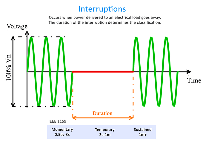
The most simple type of power quality problem occurs when power delivered to an electrical load goes away; this is called a “power interruption.” The different types of power interruptions are classified according to their duration.
-
A momentary interruption is a complete loss of voltage on one or more phase conductors for a time period between 0.5 cycles and 3 seconds.
-
A temporary interruption is a complete loss of voltage on one or more phase conductors for a time period between 3 seconds and 1 minute.
-
A sustained interruption is a complete loss of voltage on one or more phase conductors for more than 1 minute.
A power interruption occurs when power delivered to an electrical load goes away. Photo: TestGuy.
Power interruptions are caused by many different sources, such as lightning strikes, utility switching operations, physical damage to power lines, and human error. A momentary power interruption could have serious or even dangerous results depending on the connected load, such as microprocessor-based or hospital equipment.
Undervoltage, Overvoltage, Sags, Swells
The second type of power quality problem occurs when the voltage at the load drops below a minimum rated voltage or climbs above a maximum rated voltage for some period of time. Depending on how long these conditions last, they may be referred to as undervoltage or overvoltage, and sags or swells.
-
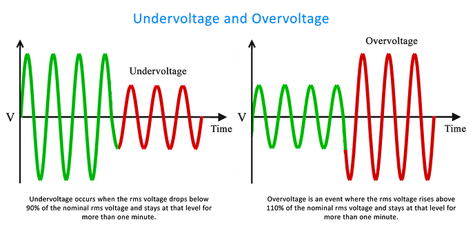
An undervoltage occurs when the RMS voltage drops below 90% of the nominal RMS voltage and stays at that level for more than one minute. The term “brownout” often refers to an intentional or unintentional drop in voltage in an electrical power supply system.
-
An overvoltage is an event where the RMS voltage rises above 110% of the nominal RMS voltage and stays there for more than one minute.
Undervoltage and overvoltage occur when voltage at the load drops below a minimum rated voltage or climbs above a maximum rated voltage for longer than a minute. Photo: TestGuy.
-
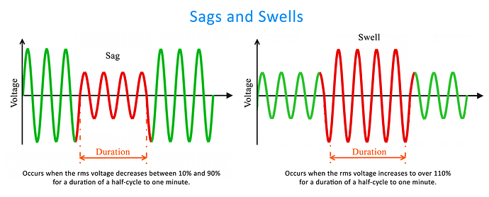
Sags occur when the RMS voltage decreases between 10% and 90% for a duration of a half-cycle to one minute. In a 60Hz power system, a complete sine wave lasts approximately 16 milliseconds, and a half cycle is approximately 8 milliseconds.
-
Swells are defined as an increase in the rms voltage to over 110% for a duration of a half-cycle to one minute.
Sags and Swells occur on the power system when voltage drops below or exceeds nominal voltage for a short duration. Photo: TestGuy.
Reductions in voltage and sags usually occur when the RMS current to the load increases significantly. There are three categories of sags and swells, depending on their duration:
- 0.5 cycles to 30 cycles: Instantaneous
- 30 cycles to 3 seconds: Momentary
- 3 seconds to 1 minute: Temporary
- 1 minute+: Sustained Undervoltage or Overvoltage
Flicker, Transients and Noise
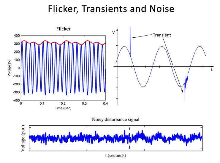
Repetitive voltage reductions in lighting circuits can be detected by the human eye, a phenomenon known as “flicker.” The term flicker refers to a very specific problem related to the human perception of light produced by incandescent light bulbs, not necessarily general voltage fluctuations.
Some common sources of flicker include: Arc welders, Electric boilers, Industrial motors, Lasers, Photocopying machines, Saw mills, and X-ray machines.
Flicker, transients, and noise examples. Photo: Various Sources.
Transients occur when spikes are superimposed on a voltage or current sine wave, ranging in amplitude from just a few volts to several thousand volts. Lightning and utility switching typically cause high-energy impulsive transients of short duration, while electronic devices, VFDs, and switching inductive loads typically cause low-energy transients continuously.
- Impulsive Transients last anywhere from 50 nanoseconds to >1 milliseconds
- Oscillatory transients last anywhere from 0.3 milliseconds to 5 microseconds
Noise refers to unwanted, high-frequency oscillations that are superimposed on an alternating voltage or current sine wave. This phenomenon is usually intensified by improper grounding and is capable of disrupting electronic devices such as computers and programmable controllers.
Power Factor, Unbalance and Harmonics
Electrical loads are often composed of more than just pure resistance; the combination of resistance and reactance in an AC system is called impedance. Reactance comes in two forms: inductive and capacitive, neither of which contributes to “useful” work on the power system.
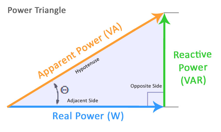
Power Factor is a way to characterize how much electrical power goes toward producing useful work such as light, heating, or machinery. A low power factor means a large amount of energy is being lost in the system in the form of wasted heat, which generally equates to higher energy bills and equipment degradation.
Three types of power - true, reactive, and apparent - relate to one another in trigonometric form. Photo: TestGuy.
Motors, solenoids, and pumps typically have impedances that are combinations of resistance and inductive reactance, which vary with the mechanical load on the machine. Capacitors have impedances that are combinations of a typically small resistance and a larger capacitive reactance component.
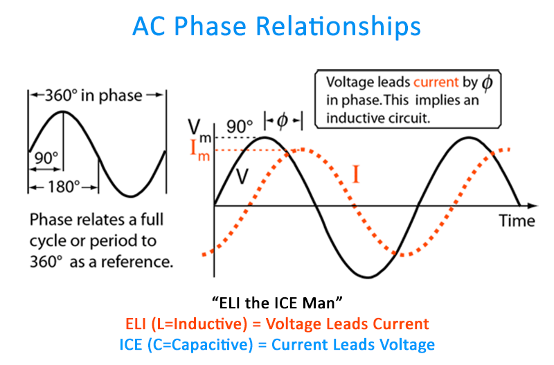
When reactance is present in an AC system, the voltage and current sine waves will shift out of phase from each other. Voltage leads current with inductive reactance, and current leads voltage with capacitive reactance; the two cancel each other out.
When reactance is present in an AC system, the voltage and current sine waves will shift out of phase from each other. Photo: Georgia State University.
Low power factor tends to occur in industrial facilities that contain a large number of motors or other inductive loads. Utility companies typically charge large industrial and commercial customers a higher rate for low power factor.
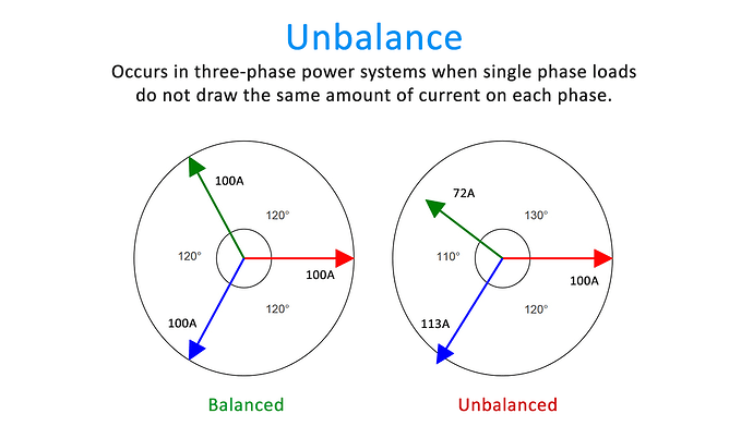
Unbalance occurs in three-phase power systems when single-phase loads (lighting, office equipment, etc.) do not draw the same amount of current on each phase, resulting in greater stress on the neutral conductor. An ideal condition occurs when the loads are balanced, meaning that the voltage and current phases are exactly 120 degrees apart from each other, although the currents might not be in-phase with the voltages.
Unbalance occurs in three-phase power systems when single phase loads do not draw the same amount of current on each phase. Photo: Sonel.
A balanced three-phase 4-wire wye system will have zero current on the neutral wire. The amount of current on the neutral wire in an unbalanced system will increase as the imbalance increases, which could result in overheating and the risk of fire.
Motors being driven by unbalanced voltages will result in a small motor torque working in the opposite direction from the motor rotation, a phenomenon known as counter-torque. When this condition occurs, part of the energy delivered to the motor will work against itself.
Harmonics are a type of waveform distortion that occurs in circuits containing semiconductor-based electronics such as LED lighting, switching power supplies, electronic ballasts, computers, robotics, test equipment, etc. These “non-linear” loads impose higher frequency sine waves on the system, resulting in more power lost in the form of wasted heat.
The excess heat produced by harmonics can have detrimental effects on a power system. Transformers are especially susceptible to damage caused by harmonics due to stray “eddy currents,” which circulate in the iron core and produce excess heat.
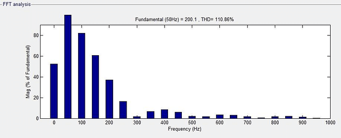
Harmonics are identified by their frequency in multiples of the “fundamental” or main frequency. Photo: Researchgate.
Harmonics are identified by their frequency in multiples of the “fundamental” or main frequency (60Hz in the United States). For example, the third harmonic in a 60 Hz system would be 180 Hz (60×3 = 180), and the 5th harmonic would be 300 Hz (60 x 5 = 300).
The magnitude of each harmonic frequency can be measured using power quality meters and is generally displayed in the form of a harmonic spectrum. Total harmonic distortion (THD) and total demand distortion (TDD) are sometimes used with power quality meters to simplify harmonic distortion as a single measurement rather than an entire spectrum.
How Power Quality is Measured
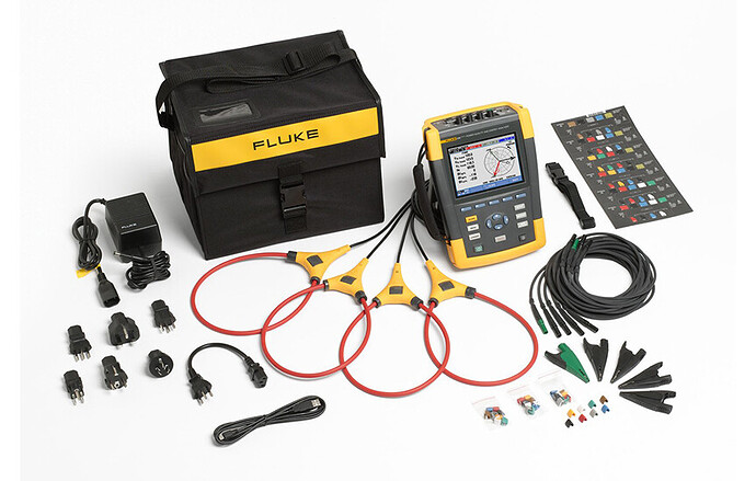
Several types of instruments are available for power quality measurement, each serving their own unique purpose. Power quality analyzers are the most commonly used tools to observe real-time readings and also collect data at high speeds for downloading to computers for analysis, as opposed to a power recorder or “data logger,” which is mainly used for simple voltage and current measurements.
Related: Test Equipment 101: The Basics of Electrical Testing
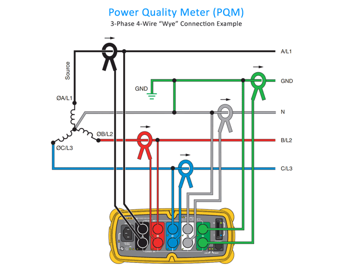
Oftentimes, power interruptions are unpredictable and of short duration, which can only be captured using a power quality meter (PQM) installed over a period of days, weeks, or months. Each phase in the system has a voltage probe and current sensor applied to monitor the magnitude and polarity of each channel over the specified period.
Several types of instruments are available for power quality measurement, each serving their own unique purpose. Photo: Fluke Corporation.
The place where the PQM is connected is called the measurement plane; everything to the right of the plane is considered part of the load, and everything to its left is considered the source. The measurement plane can be any point within the power system, not necessarily at the incoming service.
A cycle is the time that the waveform takes to travel from the zero line up to its positive peak, back down to its negative peak, and then back to zero. Power quality meters can be extremely high-speed devices designed to capture events down to the sub-cycle level.
In an ideal 60Hz system, one cycle takes 16.7 milliseconds, or 0.0167 seconds. This is called the period of the wave, and is represented by the letter T. Frequency is equal to the inverse of the period, f = 1/0.0167 = 60Hz.
Power Quality Analyzer Connection Example. Photo: Fluke Corporation.
The type of meter to install will depend on the data to be captured. For example, a simple ampere load evaluation or utility bill audit would require a far less sophisticated meter than trying to pinpoint the cause of a nuisance trip or other power interruption.
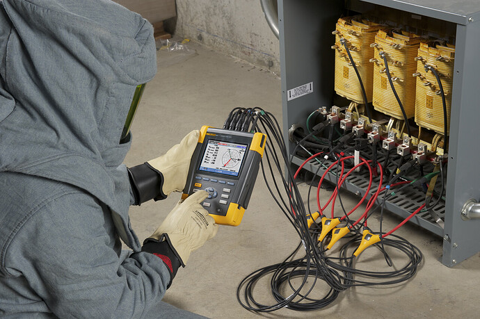
The most important factor to consider when performing power quality analysis is safety. Oftentimes, meters are applied live with equipment in service, which can be an extremely dangerous task. This type of work should only be performed by qualified personnel while observing all appropriate safety precautions. A local power outage at the monitoring location is always the safest way to install and remove a power quality meter.
The most important factor to consider when performing power quality analysis is safety. Photo: Fluke Corporation.
Power Quality Reports
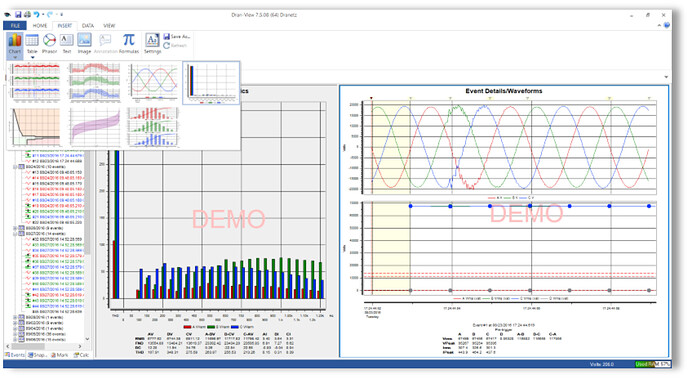
A power quality meter can plot the voltage and current waveforms as functions of time; this is called an oscillogram. Data can be extracted from the power quality recorder and analyzed to determine the overall condition of the power system using various time plots and tables.
The actual data analysis is usually performed by an electrical engineer, who will generate a report that provides a summary of the various power conditions, a list of events that occurred during the analysis, and any corrective action or recommendations that should be considered.
Data can be extracted from the power quality recorder and analyzed to determine the overall condition of the power system using specialized computer software. Photo: Dranetz BMI Dranview
Power Quality Meters are capable of calculating a large number of power measurements at extremely high speeds. These measurements may include minimum, average, and maximum values for parameters such as:
- current and voltage RMS
- phase relationship between waveforms
- power factor and frequency
- active power (kW), reactive power (kVAr), apparent power (kVA)
- active energy (kWh), reactive energy (kVArh) and apparent energy (kVAh)
- harmonic spectrum, THD, TDD
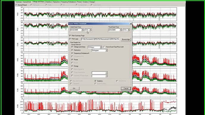
Power Quality Meters are capable of calculating a large number of power measurements at extremely high speeds. Photo: Fluke PowerLog.
Techniques for Improving Power Quality
Depending on the results of the power quality analysis, a number of recommendations can be made to improve the quality of an electrical power system. Some of the common solutions found in power quality reports are briefly described below.
-
Voltage stabilizers (or regulators) may be used to provide precise voltage regulation to protect equipment from overvoltage, undervoltage, sags and swells.
-
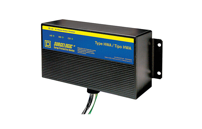
Electronic equipment should be protected from transients with surge suppressors or surge protection devices, such as SPDs or transient voltage surge suppression devices – TVSS. Surge suppressors may be installed at the service entrance panels, distribution panels and/or individual loads to protect sensitive electronic equipment.
Electronic equipment should be protected from transients with surge suppressors. Photo: Square D.
-
Snubber circuits can be used on inductive loads to suppress the transient that naturally occurs when de-energizing the load. Typical snubber circuits use a resistor-capacitor (RC) circuit, a metal oxide varistor (MOV) or a diode.
-
Noise problems can be addressed by using line filters, isolation transformers, and line conditioners. Line filters are also called electromagnetic interference (EMI) filters or radio frequency interference (RFI) filters. They should be installed at branch panels or at any sensitive electronic load such as computers and medical equipment.
-
Low power factor can be corrected with the use of capacitor banks to cancel out inductive loads. The banks may be placed at each inductive load, or they may be installed upstream to protect a group of motors, or a single compensation system may be installed at the origin of the installation. In every case, the capacitor banks correct the power factor upstream of the bank, but not downstream.
-
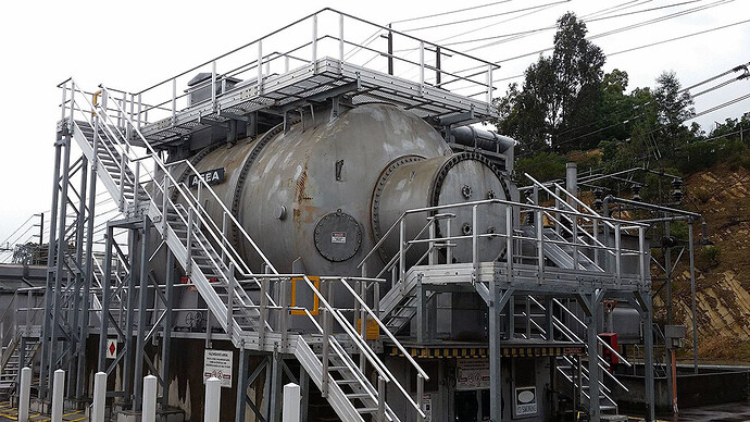
Unloaded synchronous motors can be used to continuously correct a system’s power factor by adjusting the excitation of the synchronous motor’s field. The motor can be made to behave like a variable capacitor, a device referred to as a synchronous condenser.
125MVA synchronous condenser at Templestowe substation in Melbourne, Victoria, Australia. Photo: Wikimedia.
-
Unbalance can be corrected by redistributing single-phase loads onto different circuits to minimize the maximum unbalance over some period, such as a full week. Power quality meters are used to monitor current draw on all three phases and the neutral wire for several days or weeks at a time.
-
Harmonic filters can be used to attenuate harmonic distortion to acceptable levels. Each stage of a harmonic filter is composed of capacitors, inductors, and resistors designed to attenuate a specific harmonic frequency.
Power Quality Standards
There are a number of industry standards available that address the correct procedures and methods for performing a power quality analysis. These standards should be reviewed to help better understand the science behind monitoring and correcting power quality:
- ANSI C84.1 - American National Standard for Electric Power Systems and Equipment—Voltage Ratings (60 Hz)
- IEC 61000 - IEC standards on Electromagnetic compatibility
- IEEE 519 - IEEE Recommended Practice and Requirements for Harmonic Control in Electric Power Systems
- IEEE 1159 - IEEE Recommended Practice for Monitoring Electric Power Quality
- IEEE 1250 - IEEE Guide for Identifying and Improving Voltage Quality in Power Systems
- IEEE 1668 - IEEE Trial-Use Recommended Practice for Voltage Sag and Short Interruption Ride-Through Testing for End-Use Electrical Equipment Rated Less than 1000 V
- IEEE 1789 - IEEE Recommended Practices for Modulating Current in High-Brightness LEDs for Mitigating Health Risks to Viewers
References
- Power Quality Measurement and Analysis Basics
- Electric power quality
- Why is Power Quality Analysis Done?
- FlukeView Power Quality Analyzer Software
- Fluke 1760 Power Quality Recorder Users Manual
- FLUKE Power Quality Testing Resources & Solutions
- Introduction to Power Quality: Problems, Analysis & Solutions (Archived)
- Seven categories of common power problems and their solutions
- Voltage Transients Causing Diode Failures
- Beware of asymmetry - causes, consequences, measurement and control
- Harmonic Analysis of Power Circuits by PowerSight Meters
- Technical Methods for the Prevention and Correction of Voltage Sags and Short Interruptions inside the Industrial Plants and in the Distribution Networks

