Hi,
I have measured the windings for 2 power transformers of the same type, as following:
- 1600kVA, 20/0,4kV, DYn5
For the first one I got the readings:
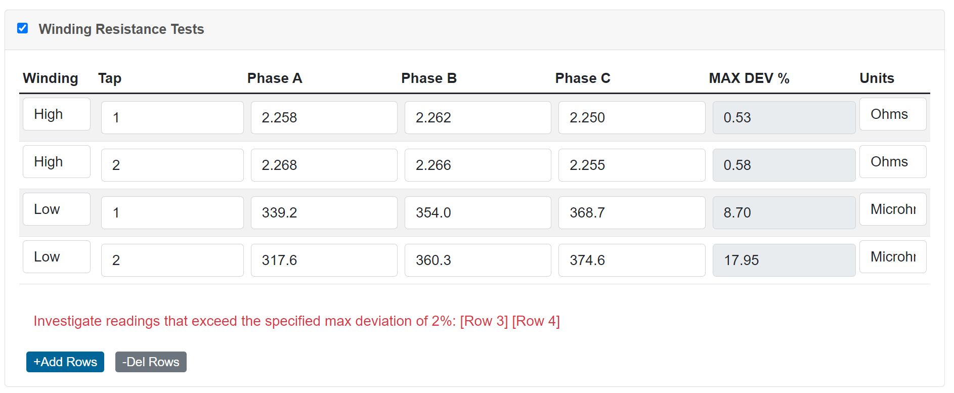
- HV side: A-B: 2,258Ω ; B-C: 2,262Ω ; A-C: 2,250Ω
- LV side: a-0: 339,2µΩ ; b-0: 354,0µΩ c-0:368,7µΩ
For the second one I got the readings:
- HV side: A-B: 2,268Ω B-C: 2,266Ω A-C: 2,255Ω
- LV side: a-0: 317,6µΩ b-0:360,3µΩ c-0: 374,6µΩ
Q1: Are these reading within the tolerances? The feeling is that on the LV side there are some differences, but not sure…
Q2: How can I calculate the tolerances - between which values ?
Thanks.
1 Like
Winding resistance values should not exceed 2% from previous values or adjacent phases.
You can calculate the percentage difference from the lowest value using this formula:
V1 - V2 / ( (V1 + V2) / 2 ) x 100
Picking some random numbers from your set, we can do the following:
2250 - 2258 / ( (2250 + 2258) / 2) x 100 = 0.35%
317.6 - 374.6 / ( (317.6 + 374.6) / 2 ) x 100 = 16.47%
The low side values do seem high when comparing to each other.
If you have access to the Pro App, there is a transformer test sheet where you can fill in your winding resistance values and it will calculate the max deviation for you: Two-Winding Transformer Test
1 Like
I suppose you could also simplify this like a ductor test where you do 1.02x the lowest value. So if you had 317.6 microhms, your max allowable value would be 317.6 x 1.02 = 323.95.
1 Like
What other investigations should be performed further on if the winding measurements are not in the 2% tollerance range (apart from repeating the measurements) ?
You will want to try and narrow down where the resistance is coming from. First investigate any bolted connections that may be loose from where the cables land to where the actual transformer windings are. You can use a DLRO for this. If you are able, try and take additional winding resistance readings as close to the winding as possible.
Also be sure you are giving the winding resistance test set enough time to settle. Sometimes the readings will take a few minutes or more to stabilize. If you take the reading to early your final results will be out of tolerance. Using a higher current setting will give more accurate results.
Is this an oil filled pad mounted transformer? Did you test any other taps? If it’s a plastic rotating tap changer, those seem to be problematic. Double check where you connected to the transformer. did you have nice solid connections?
1 Like
These numbers are consistent with what I typically get on 2000/2500 KVA transformers. I’m not saying that the data is within tolerance. However, if I condemned all the transformers that the low side was out of tolerance I wouldn’t have any customers anymore.
It’s something that my coworkers and I have been bringing up a lot lately. I believe NETA states for liquid filled transformers 2% deviation from previous data or 5% from adjacent phases. However, it is honestly a rarity that the low side of the transformer is within, or even close, to that tolerance. The high side is usually within tolerance. Most of the transformers I see are 480/277 on the low side and the readings are in microohms. I make sure the connections are consistent across phases, I test new and used transformers, and I’ve used multiple different make/model of test sets. All to produce similar results.
1 Like