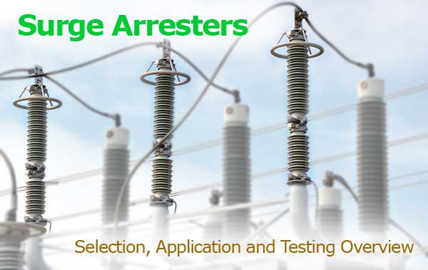
A guide to surge arrester selection, application, maintenance and testing. Photo: TestGuy.
Surge arresters are voltage-limiting devices used to protect electrical insulation from voltage spikes in a power system. Similar to how a fuse functions to protect an electrical system from damage due to overcurrent conditions, the role of a surge arrester is to safeguard the system from damage caused by overvoltage conditions.
In the past, surge arresters were called lightning arresters. This name was based on their primary objective of protecting electrical insulation from lightning strikes on the system. The more generic term “surge arrester” is now used to encompass overvoltage conditions that can occur from numerous other sources, such as switching operations and ground faults.
Everything, from personal computers to HV transmission and distribution systems, is susceptible to electrical surges and their destructive effects.
Contents
- What is an electrical surge?
- Surge Arrester Construction, Types, Classes and Properties
- Arrester Selection and Application
- MCOV Rating
- Temporary overvoltages (TOV) Rating
- Basic Impulse Level (BIL)
- Arrester Failure & Pressure Relief
- Surge Arrester Field Maintenance and Testing
- Codes and Standards
- References
What is an electrical surge?
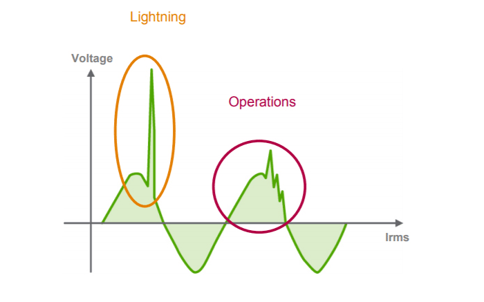
A “surge” on an electrical system results from energy being impressed on the system at some point, which can occur due to lightning strikes or system operations. The impressed energy travels throughout the system in the form of waves, with a speed and magnitude that vary along with the parameters of the system.
A “surge” on an electrical system results from energy being impressed on the system at some point, which can result from lightning strikes or system operations. Photo: Schnider Electric.
Each type of surge can affect the surge arrester and insulation system differently. Lightning results in a fast rate of rise because it’s a true source of coulomb energy, while switching operations result in a relatively slow rate of rise because their energy is stored in the magnetic fields of the system.
Along with surge phenomena, a system can also experience a longer-term overvoltage from electrical faults. Depending on the configuration and grounding of the system, a single line-to-ground fault will cause the system voltage on the unaffected phases to escalate.
Surge Arrester Construction, Types, Classes and Properties
Per the National Electrical Code (NEC), a surge arrester is defined as: “A protective device for limiting surge voltages by discharging or bypassing surge current, and it also prevents the flow of follow current while remaining capable of repeating these functions.”
The original lightning arrester was nothing more than a spark air gap, with one side connected to a line conductor and the other side connected to earth ground. When the line-to-ground voltage reached the spark-over level, the voltage surge would be discharged to earth ground.
Older surge arresters generally consist of silicon carbide resistor blocks in series with air gaps. These arresters normally carry no current and have a single voltage rating. Aside from a few exceptions, the selection of these arresters is fairly simple:
For solidly grounded systems, the next higher arrester rating above the system line-to-neutral voltage is used. For resistance grounded or ungrounded systems, the next higher rating above the system line-to-line voltage is used.
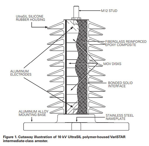
Metal oxide surge arresters contain blocks of variable resistance material, usually zinc oxide, with no air gaps. Line-to-ground voltage is applied continuously between the line and ground terminals of the arrester. These arresters do carry a minimal leakage current that can be withstood on a continuing basis.
Metal oxide surge arresters contain blocks of a variable resistance material, usually zinc oxide, with no air gaps. Photo: EATON / Cooper Power Systems.
The surge arrester’s minimal leakage current is primarily capacitive, with a small resistive component. When surges occur, the arrester immediately limits, or clamps, the overvoltage condition by conducting the surge current to ground. After the passage of the surge, the arrester returns to its initial state.
Metal oxide has many advantages as a surge protector, but it is somewhat more complicated than older surge arresters to apply correctly. Instead of a single voltage rating, metal oxide surge arresters have three ratings:
- Nominal voltage
- Maximum continuous operating voltage (MCOV) - about 85% of the nominal rating
- One-second temporary overvoltage capability. - about 120% of the nominal rating
Arrester Classes
The class of surge arrester to be applied on a system depends upon the importance and value of the protected equipment, the impulse insulation level, and the expected discharge currents the arrester must withstand.
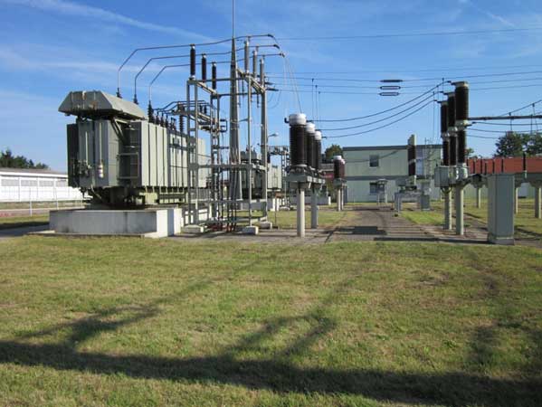
It is important that surge arresters of the correct voltage rating be used. Photo: pxhere.
-
Station class arresters are designed for protection of equipment that may be exposed to significant energy due to line switching surges and at locations where significant fault current is available. They have superior electrical performance because their energy absorption capabilities are greater. Station class arresters are the top choice for protecting valuable equipment where high reliability operation is required.
-
Intermediate class arresters are designed to provide economic and reliable protection of medium voltage class electrical power equipment. Intermediate arresters are commonly used for the protection of dry-type transformers, for use in switching and sectionalizing equipment and for the protection of URD cables.
-
Distribution class arresters can be found on smaller liquid-filled and dry-type transformers 1000 kVA and less. These arresters can also be used for application at the terminals of rotating machines below 1000 kVA, if available in the proper voltage rating. The distribution arrester is often used out on exposed lines that are directly connected to rotating machines.
-
Secondary class arresters are utilized for voltages 999V or less. These are applied in low-voltage distribution systems, electrical appliances, and low-voltage distribution transformer windings.
Arrester Selection and Application
The primary objective in arrester application is to select the lowest-rated surge arrester that will provide adequate protection of the equipment insulation and be rated such that it will have a satisfactory service life when connected to the power system.
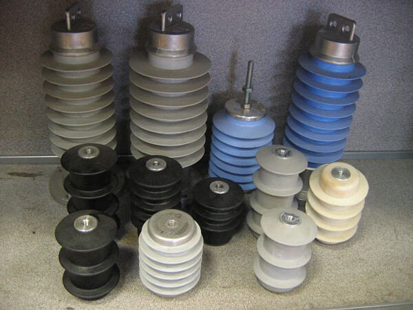
Various types of surge arresters. Photo: Wikimedia Commons.
The proper voltage rating of surge arresters depends on:
- The system line-to-line voltage
- The method of system grounding
- Type of surge arrester used
The best location for the installation of a surge arrester is as close as possible to the equipment it’s protecting, preferably at the terminals where the service is connected to the equipment. It is important that surge arresters of the correct voltage rating be used.
Equipment Protection vs. Arrester Service Life
There is a delicate balance between equipment protection and service life of a surge arrester:
-
Lower arrester ratings are preferred because they provide the highest margin of protection for the equipment insulation system but increase the chance of failure.
-
Higher arrester ratings may prolong the service life of an arrester but reduce the margin of protection provided for the equipment its protecting.
Both issues of arrester service life and equipment protection should considered when selecting surge arresters. If different ratings are required, the highest resulting surge arrester rating should be chosen.
Surge Arrester Selection and Application Process
A comprehensive surge arrester selection and application process should include a review of:
- All system stresses (continuous operating voltage, temporary overvoltages, and switching surges)
- Service conditions expected
- System-grounding configuration (grounded or effectively ungrounded) at the arrester installation location.
Knowing the system configuration (wye/delta, grounded, or ungrounded) is a key factor in selecting an arrester rating. Arrester nominal ratings for various utilization system voltages (line-to-line) are based on the system’s grounding configuration.
Choosing the correct arrester rating is critical to prevent an application where the arrester can potentially have a violent failure. Any system other than a solidly grounded configuration is considered to be effectively ungrounded, and a higher arrester rating should be chosen.
MCOV Rating
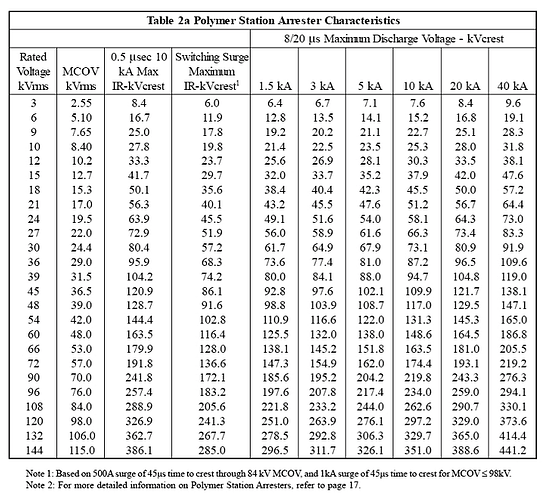
Arresters are continually exposed to the power system operating voltage during normal operation. For each arrester rating, there is a recommended limit to the magnitude of voltage that may be applied continuously. This is called the Maximum Continuous Operating Voltage (MCOV).
The arrester rating is selected so that the maximum continuous power system voltage applied to the arrester is less than or equal to the arrester’s MCOV rating. Both the circuit configuration (wye or delta) and arrester connection (Line-to-Ground or Line-to-Line) are taken into consideration.
- In most cases the arresters are connected line-to-ground.
- If arresters are connected line-to-line, then phase-to-phase voltage must be considered.
Special attention should be given to the grounding configuration of the system, either solidly grounded or effectively ungrounded (impedance/resistance grounded, ungrounded, or temporarily ungrounded). This is a key factor in the selection and application of an arrester.
If the system grounding configuration is unknown, assume the system is ungrounded. This will result in choosing an arrester with a higher continuous system voltage and/or MCOV rating.
The arrester rating is selected so that the maximum continuous power system voltage applied to the arrester is less than, or equal to, the arrester’s MCOV rating. Photo: General Electric.
MCOV Example 1: 13.8kV Solidly Grounded System
The continuous operating voltage is 13,800 divided by the square root of 3, or 7970 V. This is above the MCOV of 7,650 V for an arrester rated 9 kV.
Depending on the magnitude and duration of system overvoltages, it may be necessary to use a 10 kV arrester with an MCOV of 8.4 kV or a 12 kV arrester with an MCOV of 10.2 kV.
MCOV Example 2: Resistance-grounded 13.8 kV system
Depending on the time needed for protective relays to clear ground faults off the system, the choice will be between arresters rated 12 kV, 15 kV and 18 kV.
MCOV Example 3: 13.8kV Ungrounded System
The 12.7 kV MCOV of a 15 kV arrester is not adequate for a nominal voltage of 13.8kV. Use an 18 kV arrester with an MCOV of 15.3 kV.
Temporary overvoltages (TOV) Rating
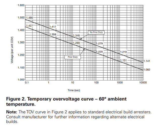
Temporary overvoltages can be caused by numerous system events, such as switching surges, line-to-ground faults, load rejection, and ferroresonance. The system configuration and operating practices are evaluated to identify the forms and causes of TOV.
The primary effect of temporary overvoltages on metal-oxide arresters is the increased current, power dissipation, and increased arrester temperature. These conditions affect the protection and survivability characteristics of the arrester.
Surge Arrester TOV curve example. Photo: EATON / Cooper Power Systems.
The surge arrester’s TOV capability must meet or exceed the expected temporary overvoltages of the system.
Basic Impulse Level (BIL) and Surge Arresters
Surge arresters are selected in coordination with standard electrical equipment insulation levels so that they will protect the insulation against overvoltages. This coordination is based on selecting an arrester that will discharge at a lower voltage level than the impulse voltage required to break down the insulation.
Related: Electrical Power System Studies Explained
Most electrical equipment is rated for impulse levels as defined by industry standards. The Basic Impulse Insulation Level (BIL) of equipment is determined by applying a full-wave voltage surge of a specified crest value to the equipment insulation; this is known as the Impulse Test.
Arrester Failure & Pressure Relief
If the service capability of a surge arrester is exceeded, the metal-oxide disk(s) may crack or puncture, reducing the arrester’s internal electrical resistance. This reduction of resistance will limit the arrester’s ability to withstand future overvoltages, but it will not jeopardize the insulation properties of the arrester.
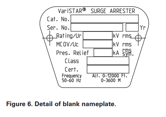
Surge Arrester Nameplate and Ratings Example. Photo: EATON / Cooper Power Systems.
In the event that an arrester fails, a line-ground arc will develop, and pressure will build up inside the arrester housing. The pressure is safely vented to the outside, and an external arc will be established, maintaining equipment protection.
Once an arrester has safely vented, it’s no longer capable of pressure relief and should be replaced immediately. Arresters should have a pressure/fault current capability greater than the maximum short-circuit current available at the intended arrester location.
Surge Arrester Field Maintenance and Testing
To help ensure maximum service life and reduce the chances of sudden failure, surge arresters should be maintained and electrically tested at regular intervals. Inspection and testing should also be performed as part of new installations prior to commissioning.
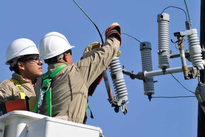
Field testing of surge arresters can help extend service life and reduce the chances of sudden failure. Photo: Senior Airman Perry Aston (USAF).
A comprehensive outline for testing surge arresters is described below. Only qualified workers with the proper safety training and calibrated testing equipment should perform these tasks.
Visual/Mechanical Inspection
The physical and mechanical condition of the surge arrester should be evaluated before any testing is performed. For new installations, compare the arrester nameplate data with project drawings and specifications.
Inspect the arrester housing, mounting, alignment, grounding, and required clearances. Surge arresters should be clean and free of obstructions to minimize contaminants that may lead to tracking or be harmful to the arrester’s insulating properties. Prior to cleaning the unit, perform as-found tests to compare results.
Related: Cleaning Methods for Electrical Preventive Maintenance
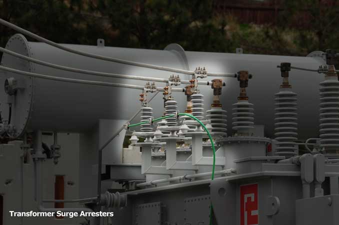
The physical and mechanical condition of the surge arrester should be evaluated before any testing is performed. Photo: Paul Chernikhowsky via Flickr.
Surge Arrester Lead Inspection
Lead length for the connection of the surge arrester to the equipment terminals and to ground should be minimized and installed as straight as possible, minimizing bends in the leads. Increases in the lead length will reduce the protection capabilities of the surge arrester due to the additional increase of impedance in the lead.
Inspect Bolted Connections
Bolted electrical connections should be inspected for high resistance by using a low-resistance ohmmeter. Compare the measured resistance values to the values of similar connections.
Values which deviate from those of similar bolted connections by more than 50 percent of the lowest value should be investigated.
Tightness of accessible bolted electrical connections may also be verified by using a calibrated torque wrench in accordance with manufacturer’s published data or NETA Table 100.12.
Related: Fastener Torque in Electrical Systems: Understanding the Basics of Mechanical Connections
Grounding Checks
Verify that each surge arrester ground lead is individually attached to a ground bus or ground electrode. Point-to-point tests can be performed to determine the resistance between the main grounding system and individual arrester ground points. The resistance between the surge arrester ground terminal and the ground system should be less than 0.5 ohm per NETA standards.
Related: 4 Important Methods of Ground Resistance Testing
Insulation Resistance
Perform insulation-resistance tests on each arrester, phase terminal-to-ground. Apply voltage in accordance with manufacturer’s literature. If the surge arrester manufacturer’s data is unavailable, NETA Table 100.1 can be used as a supplement. Values of insulation resistance less than manufacturer’s recommendations or those in NETA Table 100.1 should be investigated.
Related: Insulation Resistance Test Methods, A Beginners Guide
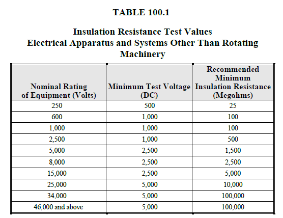
ANSI/NETA Recommended Insulation Resistance Values for Surge Arresters. Photo: NETA-MTS 2015.
Watt Loss Test
The measurement of dielectric loss is effective in detecting defective, contaminated, and deteriorated arresters. Watts loss values are evaluated on a comparison basis with similar units and test equipment manufacturer’s published data.
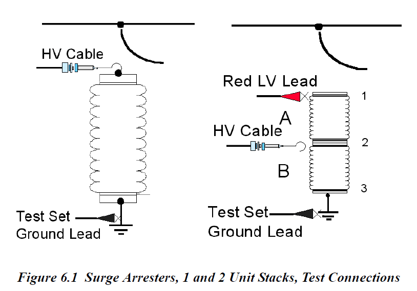
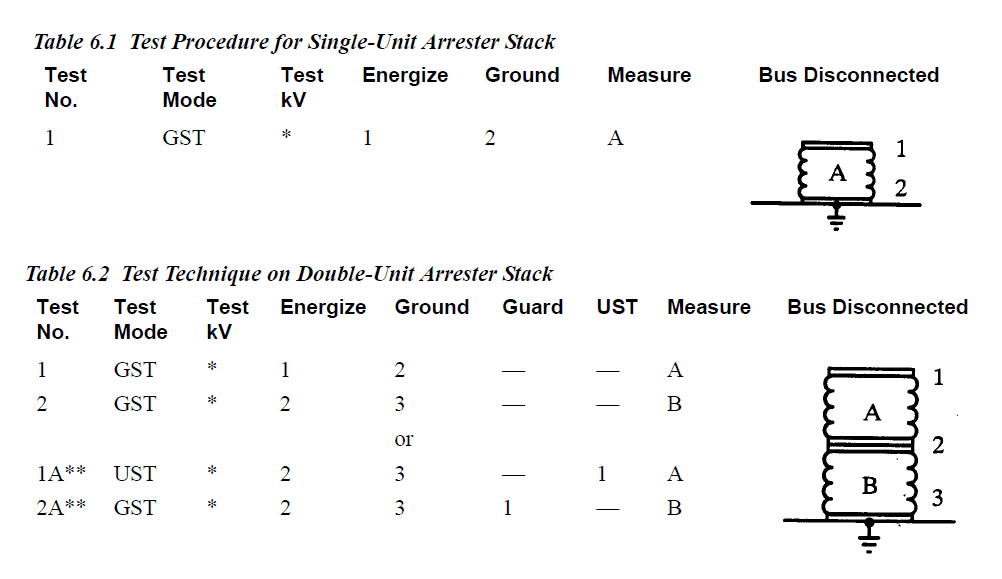
Arrester assemblies consisting of single units per phase are generally tested by the grounded-specimen test method (GST). All arresters should be tested individually and not in parallel. The watt-loss test is an optional test per NETA acceptance and maintenance testing standards.
Related: 3 Basic Modes of Power Factor Testing Explained
Surge Arrester Watt Loss Test Connections. Photo: Doble.
Surge Arrester Watt Loss Test Procedure Example. Photo: Doble.
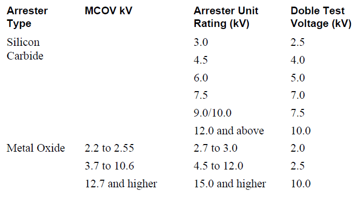
Surge Arrester Watt Loss Recommended Test Voltage. Photo: Doble.
Stroke Counter
Stroke counters measure lightning strikes by the induction of current and do not require the use of any external power source. Verify that the stroke counter, if present, is correctly mounted and electrically connected. Record the stroke counter reading to compare with previous records.
Arrester Standards and Codes
-
Surge arresters are designed and tested per ANSI/IEEE C62.1, Standard for Gapped Silicone-Carbide Surge Arresters for AC Power Circuits, for the gapped type and ANSI/IEEE C62.11, Standard for Metal-Oxide Surge Arresters for Alternating Current Systems, for the gapless type.
-
Article 280 of the NFPA 70/National Electrical Code governs surge arrester’s general requirements, installation requirements and connection requirements.
-
Surge arresters are listed by UL under the category of, Surge Arresters (OWHX), and other NRTLs (Nationally Recognized Testing Laboratories) using the applicable sections of the ANSI/IEEE standards noted above.
Related: Electrical Standards and Regulatory Organizations Explained
References
- Lightning Arresters A Guide to Selection and Application - Jude Hernandez, GE Specification Engineer
- Overvoltage protection (surge arrester) - Schnider Electric
- ANSI/NETA 2015 Standard for Maintenance Testing Specifications
- NETA ATS-2017 Standard for Acceptance Testing Specifications for Electrical Power Equipment and Systems
- Station and intermediate class surge arresters - Siemens
- History of Arresters on Power Systems 1930-1965 - ArresterWorks
- Doble Test Procedures - Revision C
- Surge Arrester Fundamentals - Cooper Power Systems 1988
