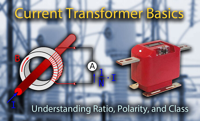
The principal function of a current transformer is to produce a manageable level of voltage and current, proportional to the current flowing through its primary winding, for the operation of measuring or protective devices.
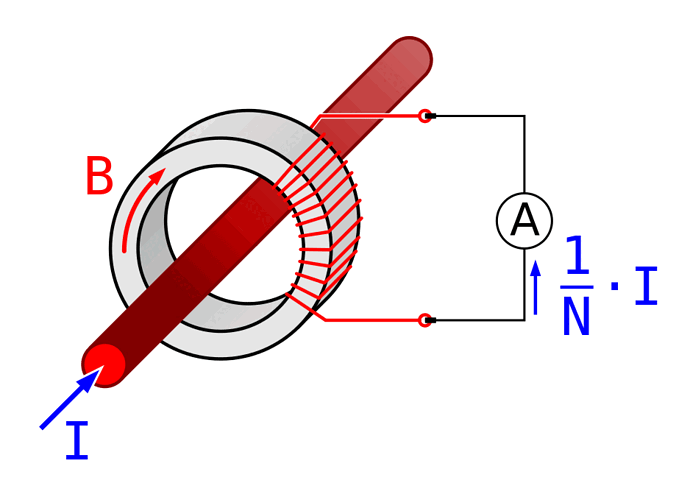
In its most basic form, a CT consists of a laminated steel core, a secondary winding around the core, and insulating material surrounding the windings. When alternating current travels through an electrical conductor, such as cable or bus, it develops a magnetic field at right angles to the flow of current.
If this current is passed through the primary winding of a CT, the iron core inside becomes magnetized, which then induces a voltage in the secondary coils. If the secondary circuit is closed, a current proportional to the CT ratio will flow through the secondary.
Basic Current Transformer (CT) Theory of Operation. Photo: Wikimedia.
Open Circuit CT
DANGER: Current transformers should remain shorted until connected to a secondary circuit. CTs are typically wired to a terminal block where shorting screws can be installed to tie isolated points together. It is important that a CT always has a burden or load connected when not in use; otherwise, a dangerously high secondary voltage can develop across the secondary terminals.
Current Transformer Types
There are four typical types of current transformers: window, bushing, bar, and wound. The primary winding can consist merely of the primary current conductor passing once through an aperture in the current transformer core (window- or bar-type), or it may consist of two or more turns wound on the core together with the secondary winding (wound type).
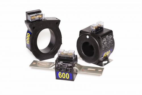
Window and Bar Type CTs are the most common current transformers found in the field. Photo Credit: ABB
1. Window CT
Window current transformers are constructed with no primary winding and can be of solid or split-core design. These CTs are installed around a conductor and are the most common CT type found in the field.
Installation of solid-core window CTs requires the primary conductor to be disconnected. Split-core window CTs can be installed without first disconnecting the primary conductor and are commonly used in power monitoring and metering applications.
Zero Sequence CTs are a type of window CT that is typically used for ground fault sensing on a circuit by summing the current on all conductors simultaneously. Under normal operation, these currents will vectorally sum to zero.
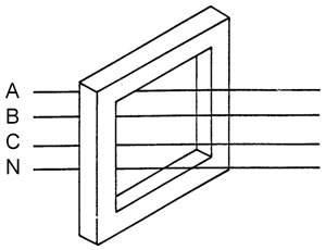
Zero-sequence Window Current Transformer
When a ground fault occurs, since a portion of the current will go to ground and not return on the other phases or neutral, the CT will see this imbalance and send a secondary current signal to a relay. Zero-sequence CTs eliminate the need to use multiple window CTs that have their outputs summed together by instead using a single CT that surrounds all of the conductors.
Related: Ground Fault Protection Systems: Performance Testing Basics
2. Bar-type CT
Bar-type current transformers operate on the same principle as window CTs but have a permanent bar installed as a primary conductor. Bar types are available with higher insulation levels and are usually bolted directly to the current-carrying device.
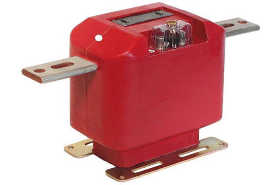
Bar Type Current Transformer. Photo: ABB.
3. Bushing CT
Bushing current transformers are basically window CTs that are specially designed to fit around a high-voltage bushing. Usually, these CTs cannot be accessed directly, and their nameplates are found on the transformer or circuit-breaker control cabinet.
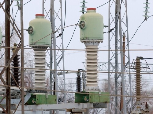
Bushing CTs cannot be accessed, and their nameplates are found on the transformer or circuit-breaker control cabinet. Photo: Wikimedia.
Related: High-Voltage Bushing Maintenance and Test Procedures Explained
4. Wound CT
Wound current transformers have a primary and secondary winding just like a normal transformer. These CTs are rare and are usually used at very low ratios and currents, typically in CT secondary circuits to compensate for low currents, to match different CT ratios in summing applications, or to isolate different CT circuits.
These type of current transformers have very high burdens, and special attention to the source CT burden should be applied when wound CTs are used.
CT Voltage Class
The CT voltage class determines the maximum voltage the CT may come in direct contact with. For example, a 600V window CT cannot be installed on or around a bare 2400V conductor; however, a 600V window CT can be installed around a 2400V cable if the CT is installed around the insulated portion of the cable, and the insulation is rated correctly.
CT Ratio
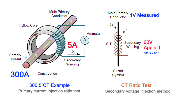
The CT ratio is the ratio of primary current input to secondary current output at full load. For example, a CT with a ratio of 300:5 is rated for 300 primary amps at full load and will produce 5 amps of secondary current when 300 amps flow through the primary.
If the primary current changes, the secondary current output will change accordingly. For example, if 150 amps flow through the 300-amp rated primary, the secondary current would be 2.5 amps.
The ratio of a current transformer is equivalent to the voltage ratio of potential transformers. Photo: TestGuy.
In the past, there were two main values of secondary current typically used in measuring current. In the United States, engineers typically use a 5-amp output. Other countries have adopted a 1-amp output.
With the advent of microprocessor meters and relays, the industry is seeing the 5-amp or 1-amp secondary being replaced with a mA secondary. Typically, devices with mA output are called “current sensors,” as opposed to current transformers.
Note: CT ratios express the current rating of the CT, not merely the ratio of the primary to the secondary currents. For example, a 100/5 CT would not fulfill the function of a 20/1 or a 10/0.5 CT.
CT Polarity
The polarity of a current transformer is determined by the direction in which the coils are wound around the core of the CT (clockwise or counterclockwise) and by which way the secondary leads are brought out of the transformer case.
All current transformers are subtractive polarity and will have the following designations to guide proper installation:
- H1 - Primary current, line facing direction
- H2 - Primary current, load facing direction
- X1 - Secondary current (multi ratio CTs have additional secondary terminals)
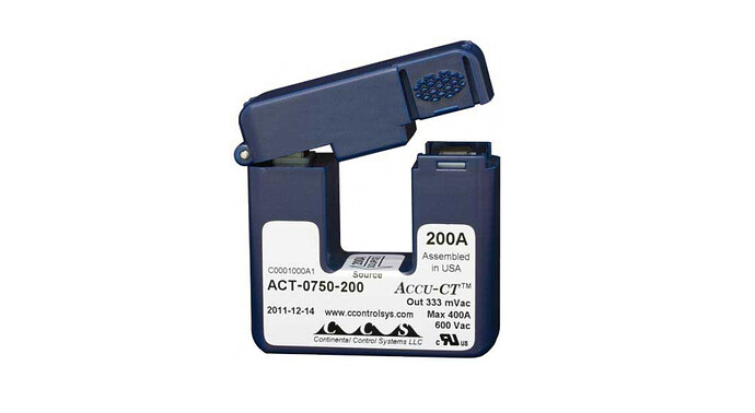
Split-Core CT rated for 200A. Notice the polarity marking at the center of the core indicating the direction of the source. Photo Credit: Continental Control Systems, LLC
On subtractive polarity transformers, the H1 primary lead and the X1 secondary lead are on the same side of the transformer. CT polarity is sometimes indicated with an arrow; these CTs should be installed with the arrow pointing in the direction of current flow.
It is very important to observe correct polarity when installing and connecting current transformers to power metering and protective relays.
CT Polarity Electrical Drawing Conventions
The polarity marking on electrical drawings and diagrams may be made for current transformers in several different ways. The three most common schematic conventions are dots, squares, and slashes. Polarity markings on electrical drawings represent H1, which should be facing the source.
Related: Electrical Drawings and Schematics Overview
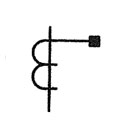
Current Transformer Electrical Symbol
How to Test CT Polarity
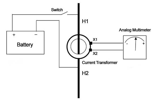
Markings on current transformers have been occasionally misapplied by the factory. You can verify the polarity of a CT in the field with a 9V battery, using the following test procedure:
-
Disconnect all power prior to testing and connect an analog voltmeter to the secondary terminal of the CT to be tested. The positive terminal of the meter is connected to terminal X1 of the CT while the negative terminal is connected to X2.
-
Run a piece of wire through the high side of the CT window and momentarily make contact with the positive end of the 9-volt battery to the H1 side (sometimes marked with a dot) and the negative end to the H2 side. It is important to avoid continuous contact, which will short circuit the battery.
-
If polarity is correct, the momentary contact causes a small deflection in the analog meter in the positive direction. If the deflection is negative the polarity of the current transformer is reversed. The terminals X1 and X2 need to be switched and the test can be carried out.
Markings on current transformers have been occasionally misapplied by the factory. You can verify the polarity of a CT in the field using a 9 volt battery.
Related: 6 Electrical Tests for Current Transformers Explained
CT Accuracy Class
Since no transformer is ideal, there are small energy losses such as eddy currents and heat caused by current flowing through the windings. The secondary current that is produced in these situations does not truly replicate the power system current waveform.
The extent to which the secondary current magnitude differs from the calculated value expected by virtue of the CT ratio is defined by the accuracy class of the CT. The greater the number used to define the class, the greater the permissible deviation in the secondary current from the calculated value (error).
Except for the least accurate classes, the CT accuracy class also defines the permissible phase angle displacement between primary and secondary currents. Depending on their accuracy class, current transformers are divided into Metering Accuracy or Protection (relay) accuracy. A CT can have ratings for both groups.
Metering Accuracy CTs
Metering Accuracy CTs are rated for specified standard burdens and are designed to be highly accurate from very low current to the maximum current rating of the CT. Because of their high degree of accuracy, these current transformers are typically used by utility companies for billing purposes.
Relay Accuracy CTs
Relay Accuracy CTs are not as accurate as Metering Accuracy CTs. They are designed to perform with a reasonable degree of accuracy over a wider range of current. These CTs are typically used for supplying current to protective relays. The wider range of current allows the protective relay to operate at different fault levels.
You can find the Accuracy Class of a CT by looking at its nameplate or manufacturers label. The CT accuracy class is comprised of a number-letter-number combination as set forth in ANSI C57.13 and is broken into three parts:
- rated ratio accuracy rating
- class rating
- maximum burden
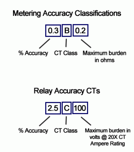
The CT accuracy class is comprised of a number-letter-number combination as set forth in ANSI C57.13
1. Rated Ratio Accuracy Rating
This number is simply the rated ratio accuracy expressed as a percent. For example, a CT with an accuracy class of 0.3B0.1 is certified by the manufacturer to be accurate to within 0.3 percent of its rated ratio value for a primary current of 100 percent of rated ratio.
2. Class Rating
The second part of the CT Accuracy Class is a letter that designates the application for which the CT is rated. A current transformer may have dual ratings and be used in metering or protection applications if both ratings are listed on the nameplate.
-
C - Indicates that the CT has a low leakage flux, which means accuracy can be calculated prior to manufacturing
-
T - Indicates that the CT may have a significant leakage flux and accuracy must be determined by the factory.
-
H - Indicates that the CT accuracy is applicable within the entire range of secondary currents from five to 20 times the nominal CT rating. These are typically wound CTs.
-
L - Indicates that the CT accuracy applies at the maximum rated secondary burden at 20 times rated only. The ratio accuracy can be up to four times greater than the listed value, depending on connected burden and fault current. These are typically window, bushing, or bar-type CTs.
3. Maximum Burden
The third part of the CT Accuracy Class is the maximum burden allowed for the CT. Like all transformers, a current transformer can only transform a finite amount of energy. The energy limitation of a CT is referred to as the maximum burden. If this limit is exceeded, CT accuracy is not guaranteed.
Metering Class Burden
For Metering Class CTs, burden is expressed as ohms impedance. For example, the ratio of a 0.3B0.1 rated CT is accurate to 0.3 percent if the connected secondary burden impedance does not exceed 0.1 ohms.
A 0.6B8 rated metering-class CT will operate within 0.6 percent accuracy if the secondary burden does not exceed 8.0 ohms.
Relay Class Burden
Relay class CT burdens are expressed as volt-amperes and are displayed as the maximum secondary voltage allowable if 20 times the CT rating (100A for a 5A secondary CT) were to flow through the secondary circuit.
For example, a 2.5C100 protection CT is accurate within 2.5 percent if the secondary burden is less than 1 ohm (100 volts / 100 amperes).
How to Calculate CT Burden
-
Determine the burden of the device connected to the CT in VA or ohms impedance. This information is typically found on the device nameplate or data sheet.
-
Add the impedance of the secondary wire run. Measure the length of the wire between the current transformer and the burden of the device connected to the secondary circuit (found in step 1).
-
Make sure the total burden does not exceed the specified limits for the CT.
