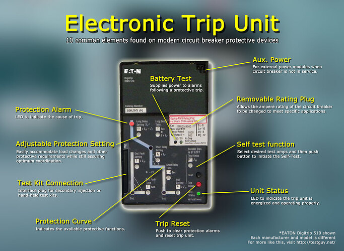
The Electronic Trip Unit is a microprocessor-controlled, multifunction overcurrent protective device for use with low-voltage power circuit breakers. The adjustment flexibility provided by electronic trip units allows users to easily accommodate load changes and other protective requirements while still ensuring optimum coordination.
In addition to the adjustable protection functions, the trip unit is designed to use field-interchangeable rating plugs. These rating plugs allow the ampere rating of the circuit breaker to be changed to meet specific applications.
Related: Characteristics of Circuit Breaker Trip Curves and Coordination
Excellent maintenance is essential for the reliability and safety of power circuit breakers. Maintenance programs must be tuned to the specific application, well-planned, and carried out consistently with both industry experience and the manufacturer’s recommendations.
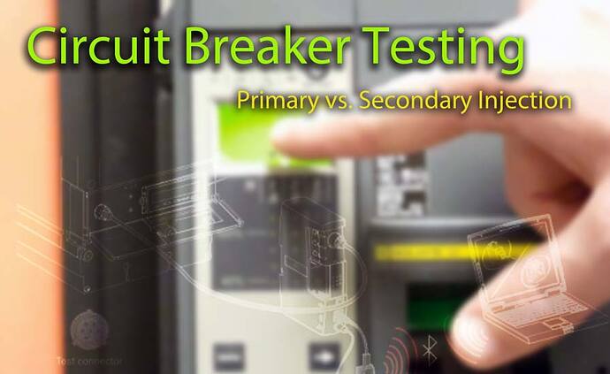
The Electronic Trip Unit is a microprocessor controlled, multifunction overcurrent protective device for application with low voltage power circuit breakers. Photo: TestGuy.
The field-testing and calibration of solid-state trip units can be performed by either the primary current injection method or the secondary current injection method. The advantages and disadvantages of each test type are briefly described below:
Primary current injection tests
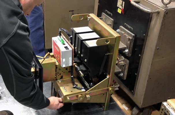
The proper functioning of the trip unit can be tested using primary current injection, one phase at a tie. Photo: YouTube.
The primary current injection method is usually the preferred test method because it includes the current sensors, wiring, and the current conduction path in the circuit breaker with the test. However, this method has one disadvantage in that it will not always detect sensor wiring and polarity problems.
This issue arises because the primary injection test is conducted on a single phase of the breaker at a time, whereas the solid-state trip logic of the circuit breaker functions by processing all of the signals from the three-phase sensors simultaneously. To identify sensor- and wiring-related problems in circuit breakers, the primary current injection test should be conducted on all three phases simultaneously when testing solid-state trip units.
If performing three-phase primary injection is not feasible, the sensors and wiring of the circuit breaker should be tested separately to verify that they are working correctly. The proper functioning of the trip unit can be tested using primary current injection, one phase at a time. Two adjacent phases may also be connected in series and tested as three pairs to check for current sensor polarity issues.
Because primary current injection testing is a relatively expensive service, it is usually performed only during the commissioning (start-up) process to supplement a program of periodic secondary-current testing. Circuit breakers that are part of a critical process or engineered safety system are often maintenance-tested using primary injection due to their high reliability requirements.
Related: The 3 Main Methods of Electrical Testing
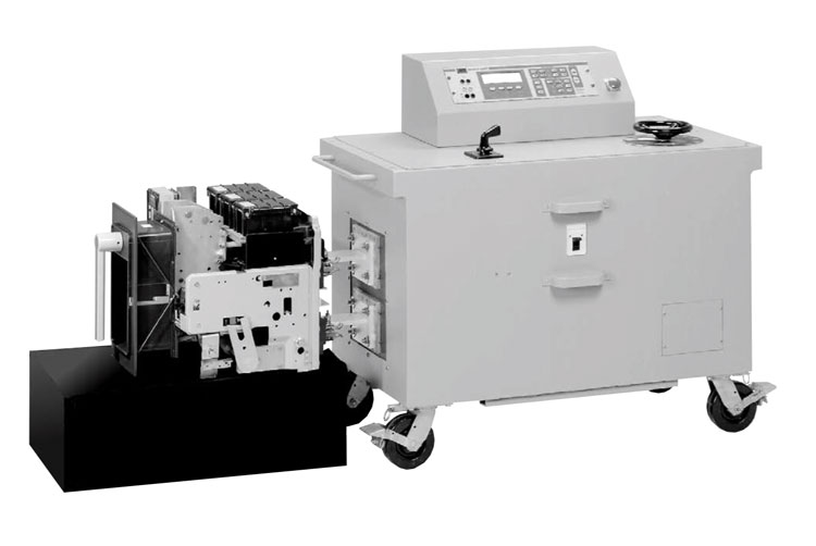
Acceptance and maintenance tests are conducted in the field using a portable primary current injection test set that is specifically designed to be more compact than factory test equipment. Photo: Megger.
Circuit breakers with thermal-magnetic or electromechanical trip units can only be verified for correct functioning via the primary current injection test method. Circuit breakers equipped with solid-state trip devices can be tested using secondary current injection, which requires less time and expense for the test.
Primary current testing is conducted by injecting a programmed sequence of overload and fault magnitude currents through a circuit breaker and documenting how long it takes the trip unit to activate. When these tests are performed at a factory or repair facility, current is injected into all three poles of a circuit breaker simultaneously.
The test set has an integrated high-current transformer that supplies the simulated overload or fault current. Test sets are built with current ratings ranging from 500 to 100,000 amperes.
Acceptance and maintenance tests are conducted in the field using a portable primary current injection test set that is specifically designed to be more compact than factory test equipment. However, these smaller test sets are generally not capable of injecting current into all three phases of a circuit breaker simultaneously.
Secondary current injection
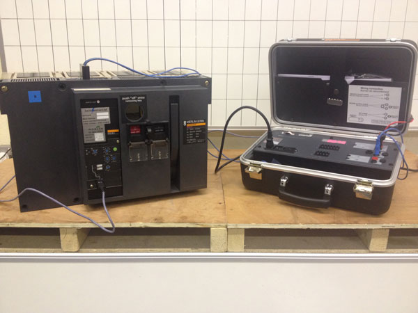
Solid-state trip units can be tested via secondary current injection using a test set specifically designed for the device to be tested. Photo: Switchserve.
Secondary current injection tests are performed for the same reason as primary current injection tests, which is to verify the correct functioning of a circuit breaker trip device during startup testing or maintenance inspections.
Solid-state trip units can be tested via secondary current injection using a test set specifically designed for the device to be tested. The main shortcoming of the secondary current injection test method is that only the solid-state trip unit logic and components are tested.
Unlike primary injection, this test method does not verify the current sensors, wiring, or circuit breaker current-carrying components. This is the main reason why the primary injection test method has superiority over secondary injection testing.
Test set connections are made directly at the solid-state trip unit, as these devices are almost universally equipped with test plug terminals for conducting the test. The secondary test set injects a simulated CT secondary current to allow checking of the trip unit operation without the need for injecting primary current through the current sensors.
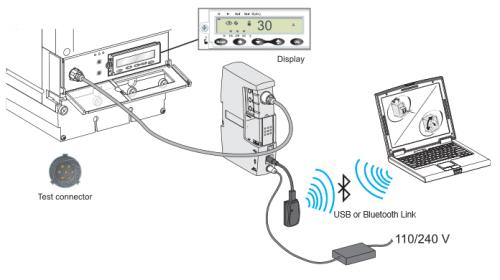
Secondary injection test set connections are made directly at the solid-state trip unit. Photo: Square D.
The circuit breaker under test must be disconnected from the bus before verifying the operation of solid-state trip units. The test set is capable of passing enough current to check any desired calibration point, and the breaker will trip during this process.
Note: For a circuit breaker that cannot be withdrawn from its compartment, an interruption of power must be expected.
If any test shows that the solid-state trip unit is not functioning properly, the trip unit should be replaced, and the defective unit labeled and removed from service until repaired. The technician conducting the test should be familiar with the instructions of the particular secondary injection test set for operating procedures to determine whether the unit has indeed failed.
Secondary Injection Test Modes
Secondary current tests can be performed on solid-state trip and electronic trip devices using various test modes, depending on the desired accuracy and outcome of the test.
1. No-trip mode
The protective functions of the electronic trip device can be tested, but the trip device won’t send a trip signal to the circuit breaker’s trip actuator. This test can be performed while the circuit breaker is energized and carrying load current because a no-trip test won’t cause the circuit breaker to open.
2. Trip mode
The protective functions of the electronic circuit are tested just like a no-trip mode test, except the trip unit will send a signal to the circuit breaker’s trip actuator. This will cause the circuit breaker to open, which is why this test is typically performed only when a circuit breaker is withdrawn from its compartment and therefore disconnected from the switchgear bus.
3. Self-test Mode
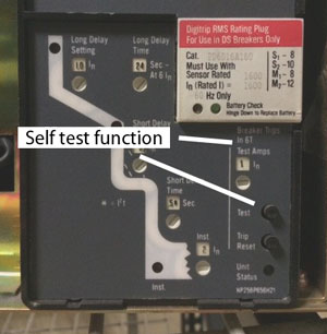
Some modern solid-state trip devices and protective relays contain integrated self-test functions that require no separate test kit. Trip unit self-tests are easier to perform than any other test and can be conducted more frequently.
The self-test function does not verify the performance of the circuit breakers current sensors and the associated current wiring. Photo: Eaton.
A trip test is best suited for troubleshooting a suspected circuit breaker malfunction. Just like with secondary current injection tests, the self-test function does not verify the performance of the circuit breaker’s current sensors and the associated current wiring.
In addition, some internal components of the trip device that carry secondary current cannot be functionally tested with the self-test. This is why self-testing is occasionally supplemented with secondary current injection testing or primary current injection testing.
Many modern solid-state trip devices constantly perform self-diagnostic checks. Potential problems with the trip unit are usually represented by a status lamp or the appearance of a fault message when detected. The trip device may also be able to communicate its alarm or fault condition via a built-in relay contact or digital communication system.
10 common elements found on electronic trip units. Each manufacturer and style will be different. Photo: TestGuy.
Related: 10 common elements found on modern solid-state trip units.
Functional testing circuit breaker electrical controls
Before installing a new circuit breaker or returning it to service after a maintenance inspection, the breaker should be placed into its compartment in the “test” position and electrically operated by closing and opening its contacts from as many control devices as practical. Checking the correct functioning of circuit breaker electrical controls verifies the integrity of control wiring, control components, and the source of control power.
Related: 10 Critical Tests for New Power Circuit Breakers
When a circuit breaker is in its test position, the closing of its main contacts will not connect the associated load circuit with the switchgear line bus. In any such case, a circuit breaker should never be tested inside its switchgear compartment while personnel are performing work on electrical equipment that is connected to the associated load circuit.
Related: Circuit Breaker Position and Indications Explained
