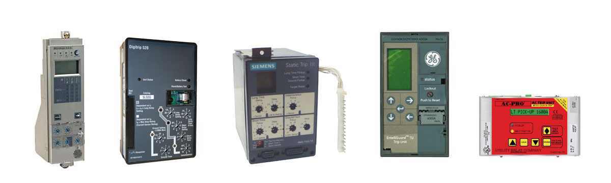
The Electronic Trip Unit is a microprocessor controlled multi-function over-current protective device for application with low voltage power circuit breakers. The adjustment flexibility provided by a trip unit allows users to easily accommodate load changes and other protective requirements while still assuring optimum coordination.
There are ten common elements found on most modern circuit breaker trip units that every electrical test technician should understand:
1. Removable Rating Plug
In addition to the adjustable protection functions, the trip unit is designed to use field interchangeable rating plugs. These rating plugs allow the ampere rating of the circuit breaker to be changed to meet specific applications.
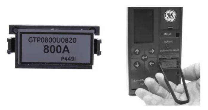
Trip Unit Rating Plug Example (GE Entelliguard). Photo: General Electric
By changing the rating plug, the User can easily change the range of current protection settings without having to remove the circuit breaker from its enclosure.
2. Protection Curve
Time-current curves are used to show the amount of time required for a circuit breaker to trip at a given over-current level. Similar to mimic bus found on a switchgear assembly, some trip units will show a representation of the protection curve on the device itself.
Related: Characteristics of Circuit Breaker Trip Curves and Coordination
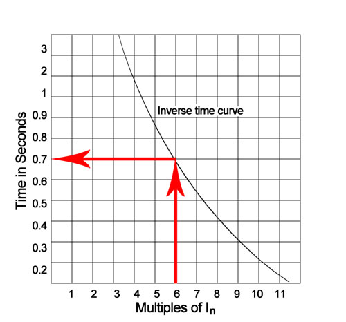
Simplified time current curve. Photo: TestGuy
3. Adjustable Protection Setting
This dial allows the user to easily accommodate load changes and other coordination requirements. Prior to placing any circuit breaker in operation, each Trip Unit protection setting must be set to the values specified by the person responsible for the installation.
4. Protection Alarm
When the protective device detects a fault that causes the breaker to trip, the protection alarm lamp will illuminate to indicate the cause of trip to personnel. Each lamp is strategically located in the related segment of the time-current curve depicted on the face of the trip unit.
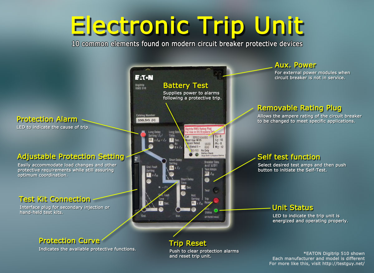
10 common elements found on electronic trip units. Each manufacturer and style will be different. Photo: TestGuy.
5. Trip Reset
After a protective trip, the trip reset button is used to clear protection alarms and reset the trip unit in preparation to be placed back into service.
6. Unit Status
Many modern solid-state trip devices constantly perform self-diagnostic checks. Potential problems with the trip unit are usually represented by a status lamp or the appearance of a fault message, when detected.
The trip device may also be able to communicate its alarm or fault condition via a built-in relay contact or digital communication system.
7. Test Kit Connection
Test connections are made directly at the solid-state trip unit, as these devices are almost universally equipped with test plug terminals for conducting the test. The secondary test set injects a simulated CT secondary current to allow checking of the trip unit operation without the need for injecting primary current through the current sensors.
Related: Primary vs. Secondary Injection for Circuit Breakers
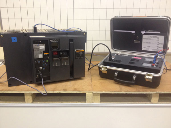
Solid-state trip units can be tested via secondary current injection using a test set specifically designed for the device to be tested. Photo: Switchserve.
8. Self Test Function
Some modern solid-state trip devices and protective relays contain integrated self-test functions that require no separate test kit. Trip unit self-tests are easier to perform than any other test and can be conducted more frequently.
9. Battery Test
Following an automatic protection trip operation, the back-up battery continues to supply power to the protection alarms. The trip unit battery is also responsible for supplying power to the device memory for other important information such as the current time, date and diagnostic data.
10. Auxiliary Power Port
This plug can be used with external power modules to maintain power on the trip unit when the circuit breaker is not in service.