Transformers are used to transfer electrical energy between circuits by stepping up or stepping down voltage levels. When engineers specify a transformer, they typically focus on details like the turns ratio, power rating, oil type, and insulation level.
However, one important aspect is often overlooked: whether it is a core-type or shell-type transformer and the number of legs in its core. In this article, we explore the differences between core-type and shell-type transformers, focusing on their construction, the role of core legs, and why these differences matter.
Core-Type vs. Shell-Type Transformers: The Basics
The main difference between core-type and shell-type transformers lies in how the magnetic core is arranged around the windings. The core is made of laminated steel and provides a path for the magnetic flux, which is essential for the transformer’s operation. The design of the core affects how the transformer handles magnetic flux, especially under certain electrical conditions.
Related: Types and Construction of Power Transformers
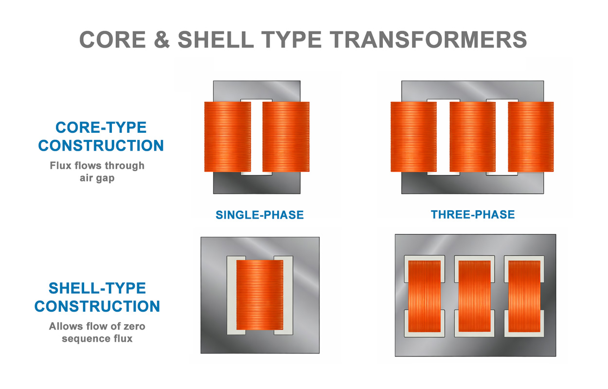
Core-Type Transformer
In a core-type transformer, the core has three legs, one for each phase in a three-phase system. The windings are wrapped around these legs, and the legs are connected by yokes (horizontal sections of the core) at the top and bottom. The magnetic flux flows through the legs and yokes, linking the three phases.
Shell-Type Transformer
In a shell-type transformer, the core has five legs. The three inner legs hold the windings, similar to the core-type design, but two additional outer legs surround the windings. This creates a “shell” that encases the windings, providing extra paths for magnetic flux.
The shell-type transformer is more complex to build because it uses more core material (iron) and has a more intricate structure. As a result, shell-type transformers are typically more expensive and harder to maintain than core-type transformers.
Zero Sequence Flux
The key advantage of a shell-type transformer lies in how it handles zero sequence flux. Zero sequence flux occurs when a transformer is exposed to zero sequence voltage, a condition where all three phases of a three-phase system have voltages that are in phase and of equal magnitude. This can happen during electrical faults, such as when a distribution line falls, causing a transformer to operate with only two phases.
In a three-phase system, magnetic flux normally flows between the phases through the core legs and yokes, balancing out the magnetic field. However, zero sequence flux behaves differently because it does not cancel out between the phases. Instead, it seeks a path outside the windings to complete its magnetic circuit.
Flux Paths
The two extra outer legs in a shell-type transformer provide a dedicated path for zero sequence flux. These legs guide the flux around the windings and back to the core, keeping it contained within the core material.
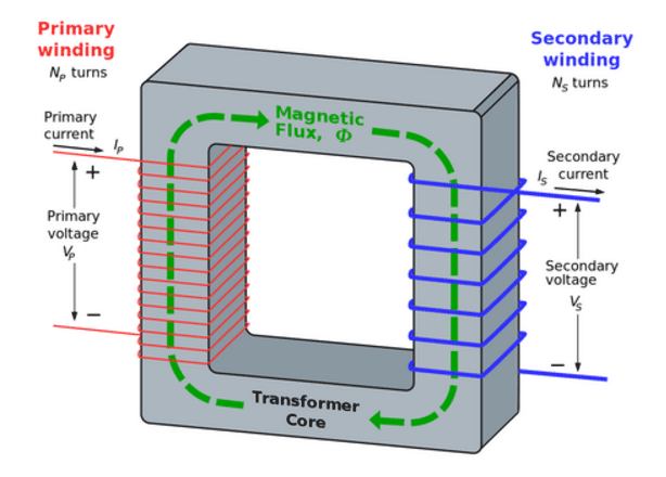
When the primary winding of a transformer is energized with an alternating current (AC), alternating magnetic lines of force, called “flux,” circulates through the core, establishing a magnetic field. Photo: Quora
Related: Transformer Turns Ratio (TTR) Explained
In a core-type transformer, there are no outer legs to guide zero sequence flux. As a result, the flux must find another path to complete its circuit. This often means traveling through the transformer’s oil, tank walls, or other nearby metal components.
Inductive Heating
When zero sequence flux flows through unintended paths, such as the transformer’s tank walls, it can cause serious problems. The magnetic flux induces eddy currents in the metal tank, which generate heat through a process called inductive heating.
Prolonged exposure to this heating can cause the tank walls to become extremely hot leading to the breakdown of the transformer’s insulating oil. When the oil degrades, the transformer’s insulation fails, causing the transformer to malfunction or catastrophically fail.
Related: Insulating Liquids: Basic Properties, Types and Applications Explained
Zero sequence flux is most likely to occur during electrical faults. For example, if a utility’s distribution line falls, a transformer may receive power from only two phases instead of three.
This unbalanced condition can create zero sequence voltage, leading to zero sequence flux. If the transformer is a core-type design, the flux will flow through the tank walls, causing overheating and potential failure.
Conclusion
Engineers may overlook the core-type vs. shell-type distinction when specifying transformers, especially if they rely on standard specifications or choose the less expensive core-type design. While core-type transformers are simpler and cheaper, they are less equipped to handle zero sequence flux.
When selecting a transformer, it’s important to consider not only the turns ratio, power rating, and insulation but also the core design. Shell-type transformers (with their additional legs) are better suited for applications where electrical faults or unbalanced conditions are a concern, such as in utility distribution systems.
Core-type transformers are simpler and less expensive but may struggle with zero sequence flux during electrical faults. Shell-type transformers provide a robust solution by containing zero sequence flux within the core, preventing overheating and potential failure.