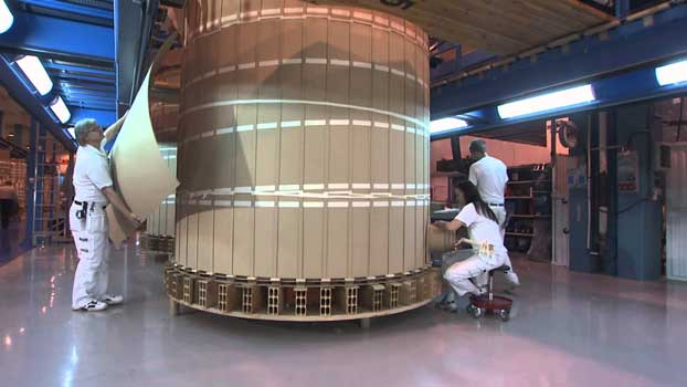
Transformer windings are formed with precision around a large spool, with each number of turns dependent on the voltage ratio of the transformer being constructed. Photo: Siemens
In industrial installations, transformers are mainly used to step down a higher distribution level voltage to a lower utilization level. They are vital links in electrical power systems and are among the most reliable components in the system.
Transformers can be divided into two general categories according to their insulating medium and construction: liquid-filled and dry-type. Each has several variations and each requires different maintenance techniques.
Core and Coil
No matter what the type, any transformer construction starts with the core and coil assembly. It is here where thin metal sheets are stacked (laminated) to prepare the magnetic body known as the core. The purpose of the iron core is to channel the magnetic flux generated by the current flowing around the primary coil, so that as much of it as possible also links the secondary coil.

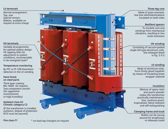
No matter what the type, any transformer construction starts with the core and coil assembly. Photo: Siemens
The windings are manufactured from copper or aluminum conductors, separated by layers of insulation. Each conductor is formed with precision around a large spool, with each number of turns dependent on the voltage ratio of the transformer being constructed.
The iron core is enclosed by the low voltage coil and enclosed again by the high voltage coil, connection points are welded at each end, and brought out from each winding to allow for the installation of cable or bus.
Voltage Taps
Optional voltage taps may be installed on the primary windings to regulate the output voltage of the transformer. It does this by altering the number of turns in the winding and thereby changing the turns ratio of the transformer.
Taps often have 5 positions (A,B,C,D,E, or 1,2,3,4,5) and are changed either by physically moving jumpers between terminals on the winding or by a selector switch. In any case, the taps cannot be moved while the transformer is energized (referred to as a “de-energized” tap changer).
With the key components of the transformer completed, now the entire core and coil assembly must be enclosed and insulated before it can be safely utilized in the field. The type of enclosure and insulation to be used will be determined by the application, commonly specified by the customer or engineer.
Liquid Filled Transformers
The core and coils of liquid-filled transformers are, as the name implies, immersed in a liquid. The liquid serves two purposes. First, it is the fundamental element of the insulating system. Second, liquid transfers heat away from the windings to be dissipated by the cooling fins, tank surface, or radiator.
Without sufficient liquid surrounding the coils, energized and current-carrying components will be exposed and could result in overheating or an electrical flashover. If the oil level is too high, it could cause an over pressure condition inside the transformer tank as temperatures change.
A positive seal of the transformer liquid may be provided by an inert-gas system. Here, the tank is slightly pressurized by an inert gas such as nitrogen.

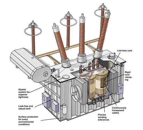
The core and coils of liquid-filled transformers are, as the name implies, immersed in a liquid. Photo: ABB
There are four types of insulating liquid that technicians are likely to encounter in the field:
- Mineral oils (petroleum based)
- Natural esters (derived from renewable natural sources)
- Askarel (contains PCB)
- Silicone or stabilized hydrocarbon liquids (less flammable liquids)
Each liquid has definite characteristics, and they SHOULD NOT be mixed. Manufacturers’ instructions and Safety Data Sheet should be carefully followed with all insulating liquids.
Askarel is identified by various brand names and consists largely of polychlorinated biphenyls (PCBs). It is subject to strict government regulation as a toxic substance. A knowledge of government regulations is necessary because any liquid-filled transformer might contain some level of PCBs.
Power Transformer Liquid Preservation Techniques
There are several types of transformer construction regarding the preservation of the liquid. Preservation means minimizing exposure of the insulating liquid to the atmosphere. The types are as follows:
- Free breathing (open to the atmosphere)
- Restricted breathing (open to the atmosphere through dehydrating compounds)
- Conservator or expansion tank (exposure to air limited to the liquid in the conservator tank)
- Sealed tanks (a gas space above the liquid serves as a cushion for internal pressure)
- Gas–oil seal (exposure to air limited to the oil in the auxiliary tank)
- Inert gas (gas space above liquid maintained under positive pressure by gas supplied from a nitrogen cylinder)
Liquid Transformer Cooling Systems
The power transformer cooling system is critical to good transformer health. If the heat inside of a transformer is not properly dissipated, the temperature of that transformer will rise continually, which will damage the insulation over time. A transformer operating at just 10°C above its rating will reduce its life by 50%.
Some common methods used to dissipate heat with liquid filled transformers include:
- Self-cooled (ONAN) — heat is dissipated by the tank surface and cooling fins or tubes.
- Forced-air cooled (ONAF) — fans are employed to force air over the cooling surfaces to augment the self-cooled rating.
- Forced-air cooled/forced-oil cooled (ONAF/OFAF) — an oil pump circulates oil through a fan-blown oil-to-air heat exchanger.
- Water cooled (OFWF) — heat exchange by means of water pumped through a pipe coil installed inside or outside the transformer tank.
Dry Transformers
Dry-type transformers operate in air or gas rather than being liquid filled. Just like with liquid transformers, the air or gas serves as an insulating medium and also to dissipate heat from the windings. The two general types of construction are the open or ventilated dry-type transformer and the sealed or closed-tank type.

It is important to keep dry-type transformer enclosures clean and the area around them clear.
Ventilated dry-type transformers are usually varnish impregnated or cast coil construction.
Varnish Impregnation
With varnish impregnation, the spaces between the coverings and the turns of the electrical winding is thoroughly coated with varnish and the varnish coating is then thoroughly cured to provide optimum insulating and thermal conducting properties as well as being imperviousness to moisture and sufficient strength to resist fracture of the coating.
Cast coil
Cast coil transformers are manufactured by “casting” them into a solid block by combining the coils with a cast resin in a vacuum furnace. This manufacturing process makes the transformer more resistive to heat and less susceptible to fire.
Sealed Tank
Sealed transformers are cooled and insulated by a high-dielectric inert gas, such as nitrogen or sulfur hexafluoride. The construction of a sealed transformer is basically the same as an liquid filled transformer, with the only exception being the insulating material and cooling medium.
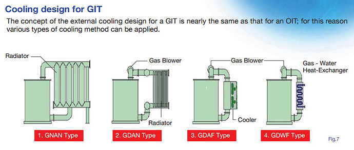
The cooling design of a Gas Insulated Transformer is nearly the same as that for an Oil Insulated Transformer. Photo: Toshiba.
Gas Insulated
Gas insulated transformers (GIT) are compact and cost effective. They are desirable for use in urban areas where space is limited and safety is the most important consideration. The concept of the external cooling design for a GIT is nearly the same as that for an oil-filled transformer.

