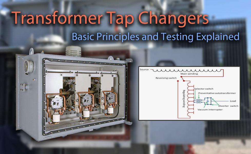
Electrical energy is unique in that it must be constantly produced at a rate that meets instantaneous demand. Consequently, transformers must adapt to rapidly changing conditions on power grids by regulating their voltage output.
Transformers efficiently transfer electrical energy from one circuit to another by means of magnetic induction. Each phase of a transformer is composed of two separate coil windings wound on a common core.
The easiest way to change the output of a transformer is by either changing its input voltage or by changing the number of turns in the windings. Tap changer switches provide an external means to accomplish this voltage adjustment.
De-Energized Tap Changer (DETC)
Many electrical transformers are equipped with a manually operated tap changer switch on the high-voltage winding known as a DETC or de-energized tap changer. This switch enables operators to adjust the number of turns in the high-voltage winding based on the connected system input.
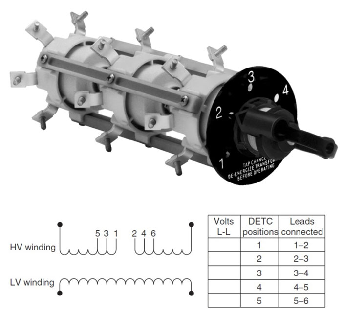
Transformer De-energized Tap Changer Switch Example. Photo: EATON.
As the name “de-energized” implies, these voltage adjustments can only be made when the transformer windings are isolated because the switch is not designed or rated to interrupt high-voltage electrical loads. Adjustments on a DETC are typically made only for seasonal weather changes and require an electrical outage.
The de-energized or off-load tap changer is usually mounted on the main transformer tank and is set to match the high-voltage network supplying the transformer. It often has five positions (A, B, C, D, E, or 1, 2, 3, 4, 5). If a DETC is not regularly exercised, there is an increased risk that the switch contacts will not make properly when next moved.
Load Tap Changer (LTC)
For a transformer to adapt to various operating conditions at any given time, a different type of tap changer design is necessary. The On-Load Tap Changer (OLTC or LTC) is designed to change positions several times a day to compensate for daily shifts in load conditions without interrupting the nominal output power supply.

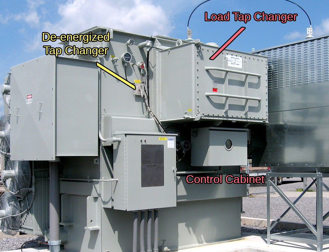
Transformer Load Tap Changer Example. Photo: ABB.
LTCs can be internal to the main tank or contained within a separate, sealed liquid-filled compartment with feed-through tap connections located on the rear panel. Externally mounted load-tap changers are typically welded around a cutout on the transformer tank where tap connections are made to a regulator winding that is connected in series with the transformer low-voltage winding.
Control circuitry enables operators to assess the need for a raised or lowered tap change operation to maintain output voltage. Selector switches facilitate changing the physical tap position on the transformer’s regulating windings, but they do not make or break the circuit load current.
On load tap changers may be generally classified as either mechanical, electronically assisted, or fully electronic.
Load Tap Changing Transformer. Photo: Niagara Power Transformer.
A mechanical tap changer physically makes the new connection before releasing the previous by using multiple tap selector switches. High circulating currents are avoided by using a diverter switch to temporarily place a large impedance in series with the short-circuited turns.
A high-speed resistive type OLTC utilizes a resistor pair to absorb energy and does not utilize the bridging position as a service position. In a resistance-type tap changer, the transition to another tap must be executed swiftly to prevent overheating of the diverter circuit.
A reactance type tap changer uses a dedicated preventive autotransformer winding to function as the diverter impedance. The preventive autotransformer acts as a current-limiting device when the LTC is on, or passing through, a bridging tap position.
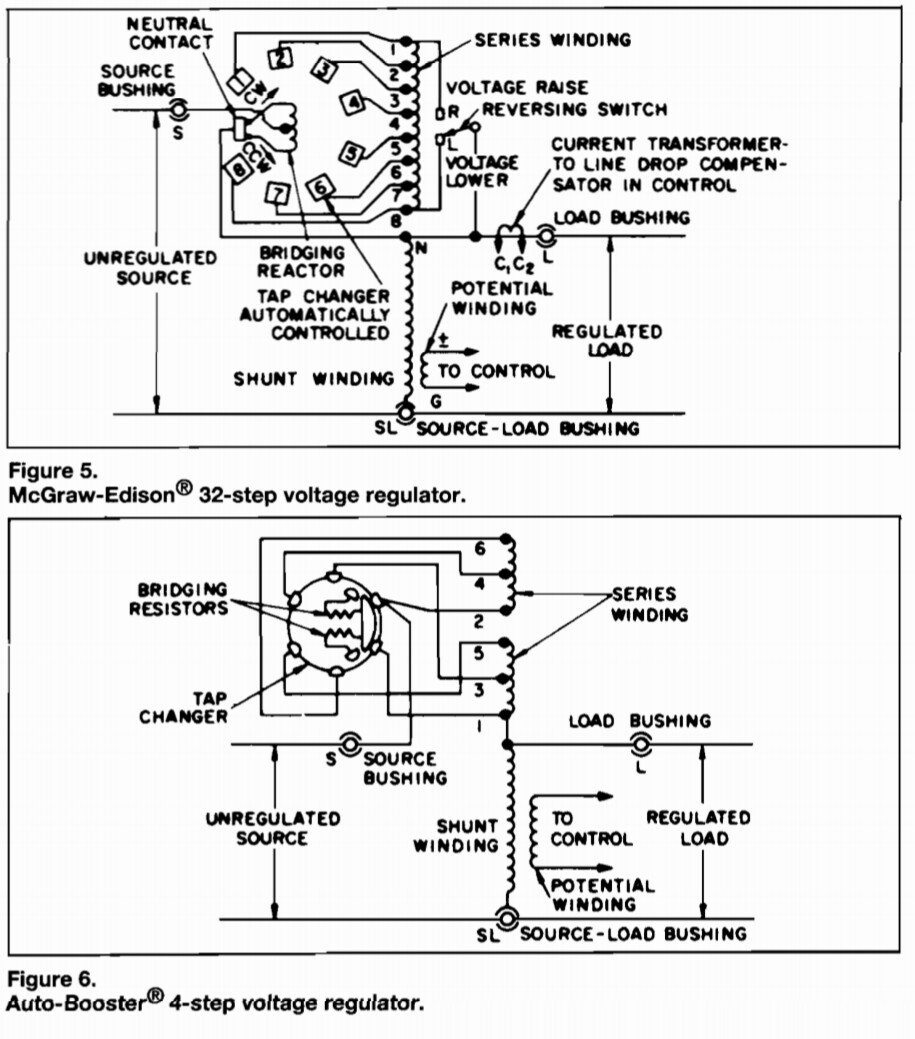
32-Step and 4-Step Voltage Regulators. Photo: McGraw-Edison.
Load Tap Changer Operation
Since the load current must never be interrupted during a tap change, there is an interval where two voltage taps are spanned. The PA (also known as bridging a reactor) is used in the circuit to increase the impedance of the selector circuit and limit the amount of current circulating due to this voltage difference.
The operating mechanism for most load tap changers is motor-driven, but manual operation can be employed in the event of motor failure. The sequence of operation is mechanically interlocked to ensure that all contacts will always operate in their correct order. Any failure of the operating mechanism can result in severe damage to the transformer and tap changer.
A standard 32-step LTC comprises 16 raise positions and 16 lower positions. The physical taps are situated on a regulating winding within the main transformer tank, which is connected in series with the main winding via a reversing switch.
Voltage is increased or decreased by movable contacts that employ a “stepping” action to move from one connection to the next, thereby adding or subtracting turns on the regulating winding. The raise or lower mode is dependent on the polarity of the connection through the switch.
The neutral position is the normal position where the LTC is neither raising or lowering voltage and/or where the tap windings are not in the circuit. The neutral position is the only position where the reversing switch is not carrying current.
Transformer Tap Changer Testing
Tap changers have historically been one of the leading causes of transformer failures. Faults in OLTCs can be classified as dielectric failures (related to oil quality or insulation), thermal failures (due to poor terminations), or mechanical failures (such as contact wear, misalignment, sheared linkage, lubrication problems, etc.).
Routine inspection and maintenance of load tap changers is the best defense against premature failure when performed at regular intervals. Analysis of the tap changer insulating fluid can help detect overheating and excessive arcing without the need for internal inspection.
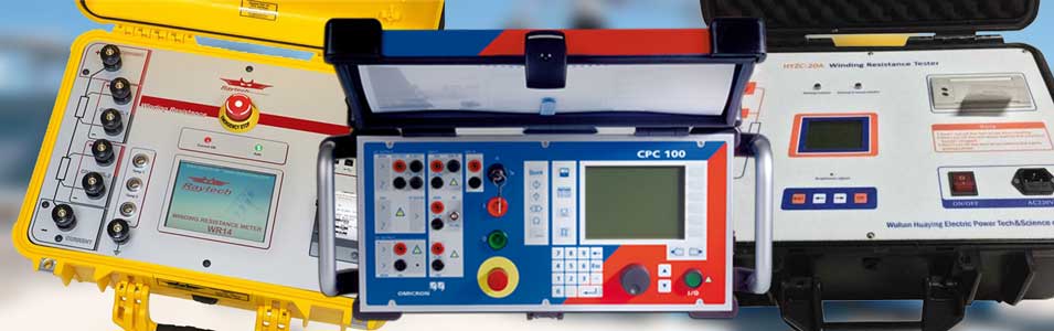
Transformer Testing Equipment. Photo: TestGuy.
Electrical tests can be performed on tap changer components to compliment oil analysis and further detect problems that might not show up with just an oil test.
Exciting current tests are capable of detecting a wide range of transformer tap changer problems in both de-energized and on-load tap changers. Mechanical issues such as misalignment, contact wear, loose connections, open- or short-circuited turns, and much more can be identified through these tests.
DC winding resistance is a valuable test for detecting potential problems with the current-carrying path of a transformer circuit. It can identify loose electrical connections and pinpoint partial open-circuited conditions by applying a known DC current and measuring the voltage drop between each test point.
Dynamic winding resistance is another test that measures DC current and resistance as a function of time as the OLTC changes tap position. This test is best used to identify potential problems with the diverter circuit or transition resistors of an OLTC during operation.
The turns ratio of each tap should also be checked when measuring the ratio of the main transformer windings. When performing Sweep frequency response analysis (SFRA) on transformers, the mechanical integrity of the tap windings and their leads are included with the mid- to upper-frequency ranges.
The frequency of tap changer inspection and testing varies depending on the environmental and physical conditions of the equipment, as well as the criticality of the tap changer and associated transformer in relation to the overall power system. Since tap changers are mechanical devices, it is recommended to take an oil sample each year, with electrical testing performed at least every two years.