The transformer turns ratio test is used to determine the number of turns in one winding of a transformer in relation to the number of turns in the other windings of the same phase of the transformer.
The transformer polarity test determines the vectoral relationships of the various transformer windings. The transformer ratio test serves as both an acceptance test and a maintenance test, while the polarity test is primarily an acceptance test.
The test equipment used is ordinarily a turns ratio tester designed for the purpose. If not available, input and output voltages can be measured, using voltmeters with at least 0.25 percent full-scale accuracy, for approximation.
When a turns ratio test of the transformer is performed, the ratio should be determined for all no-load taps. If the transformer is equipped with a load-tap changer (LTC), the ratio should be determined for each LTC position. If the transformer has both an LTC and a no-load-tap changer, then the ratio should be determined for each position of the LTC to one position of the no-load-tap changer and vice versa.
This test is useful in determining whether a transformer has any shorted turns or improper connections. In acceptance testing, it also verifies nameplate information.
Related: Transformer Tap Changers: Basic Principles and Testing Explained
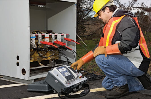
The turns ratio test is used as both an acceptance test and a maintenance test, while the polarity test is primarily an acceptance test. Photo: Megger
Safety Considerations
When testing transformers, caution must be used at all times. Observe all safety precautions and follow OSHA lockout/tag out procedures before testing. Be certain that the transformer to be tested is completely de-energized. Check every winding. The procedures in the article should only be performed by workers who are qualified to service high voltage equipment.
Transformer Turns Ratio Test Connections
When testing a transformer for turns ratio, the connections are determined by matching parallel vectors.
Transformer turns ratio test sets come in a variety of styles and test connections; however, all turns ratio testers have at least two high leads and two low leads. Basic setup procedures are explained below; consult the test set user manual for your specific setup instructions.
Make certain that all terminals of the transformer are disconnected from the line or load at the transformer. Connections to ground may be left in place if desired. Verify test set performance via preliminary checks before testing; consult the user manual for your specific tester.
Single-Phase Models
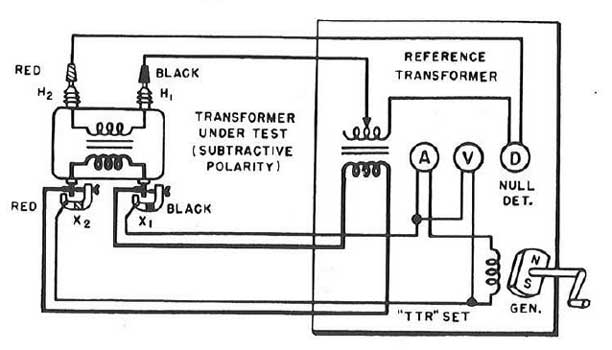
Transformer ratio test diagram, using a Single phase TTR test set. Photo: Megger.
Connect the exciting leads (X1 and X2) to the lower-voltage winding of the two windings to be compared. Match transformer polarity by connecting the H1 secondary lead to the higher-voltage terminal corresponding to the X1 connection. See Figure.
Connect the H2 lead to the other high voltage terminal. Where both windings are grounded on one side, connect X1 and H1 to the grounded sides.
Always excite the entire low-voltage winding. For polyphase transformers, repeat the procedure on each set of windings to be measured.
Three-Phase Models
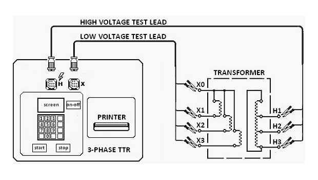
Three-phase TTR testing connection diagram. Photo: EEP.
Connect the H0, H1, H2, and H3 test cables to the corresponding high-voltage winding terminals of the transformer under test. With delta-connected windings, H0 is not used.
Connect the X0, X1, X2, and X3 test cables to the corresponding low-voltage winding of the transformer under test. With delta-connected windings, X0 is not used.
It is possible to test single-phase two-winding transformers with a three-phase TTR test set by only utilizing the H1, H2, and X1, X2 leads.
Transformer Turns Ratio Test Values
Turns ratio test results should not deviate by more than one-half percent from either the adjacent coils or the calculated ratio. Test values outside of this tolerance may indicate a shorted or open transformer winding. Check all test set connections and perform a self-test on the TTR, and retest if necessary.
References
- Transformers: Basic, Maintenance and Diagnostics – U.S. Department of the Interior
- NFPA 70B: Recommended Practice for Electrical Equipment Maintenance, 2016 Edition
- Megger 550005 Series TTR Instruction Manual
- Megger TTR330 series TTR Instruction Manual
- Megger TTR300 series TTR Product Sheet
- ANSI/NETA Standard for Acceptance Testing Specifications for Electrical Power Equipment and Systems 2013
- ANSI/NETA 2015 Standard for Maintenance Testing Specifications