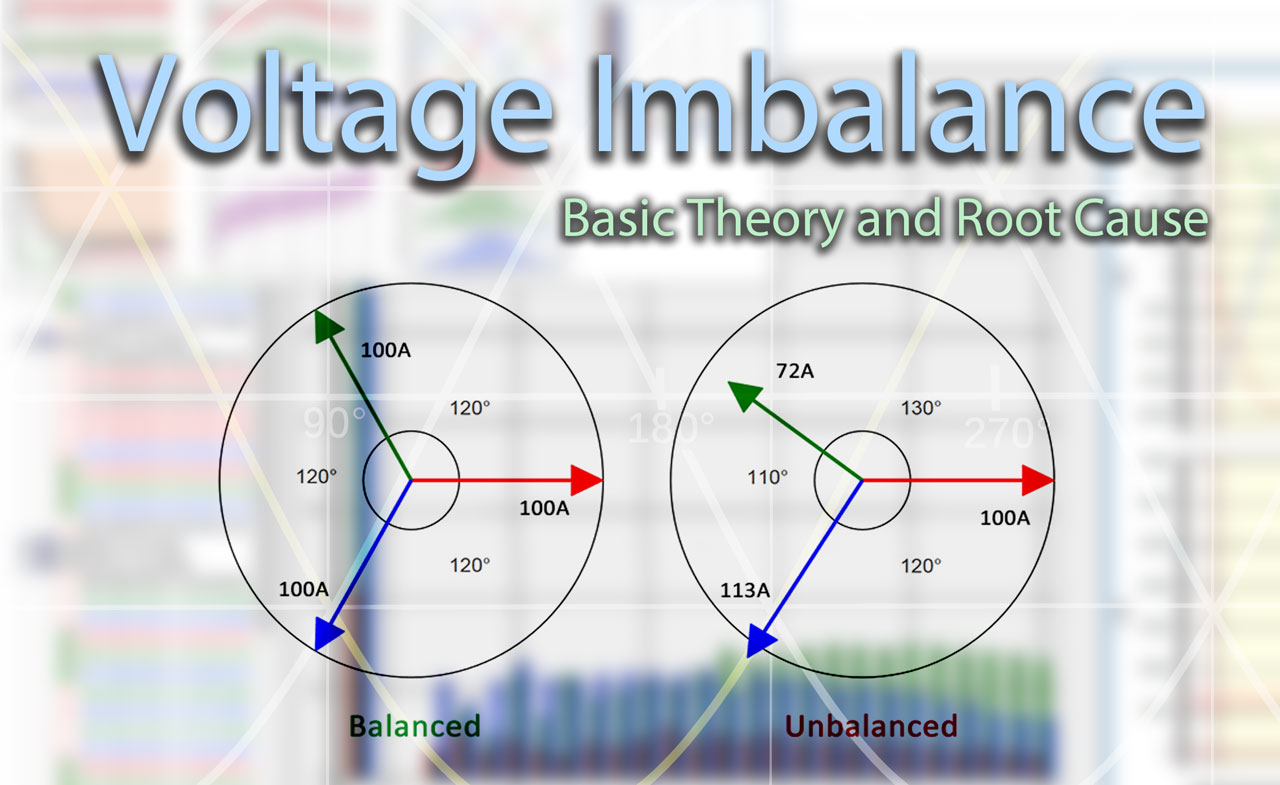
Maintaining quality power is fundamental to keeping electrical transmission and distribution systems running efficiently. Voltage imbalance directly degrades power quality by increasing heating in motors, accelerating insulation aging, and triggering nuisance trips in sensitive electronics.
Voltage imbalance is defined where the three-phase voltages deviate from equal magnitude and 120° separation. Even imbalances as small as 2–3 % can cut motor life by half and raise system losses.
Identifying the root causes of voltage imbalance is the first step utilities and engineers can take to prevent these damaging effects. In this article, we discuss eight common scenarios that can lead to unbalanced voltage conditions:
1. Current imbalance on a feeder due to differing single-phase loading
Distribution feeders often serve a mix of single-phase residential and commercial loads that are not evenly distributed across the three phases. When one phase carries significantly more load the current flow becomes unbalanced. This unequal current produces unequal voltage drops along the line impedance, shifting the phase voltages at downstream customers.
Conditions such as a larger number of laterals, unequal tap connections, or feeders branching unevenly can result in imbalance. The imbalance worsens over time during peak loading periods, creating persistent voltage deviations.
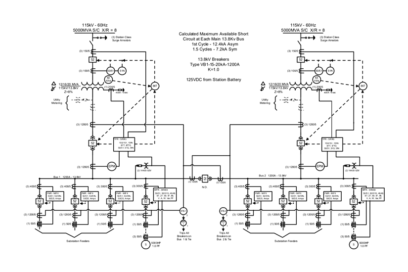
Medium-Voltage Switchgear One-Line Diagram. Photo: General Electric
2. Single-phase distributed generation such as single-phase solar and wind
Rooftop solar inverters and small wind turbines frequently inject power into only one or two phases of the distribution system. The sudden injection of real power on a single phase alters the local power flow without a corresponding contribution on the other phases.
This creates a voltage rise on the loaded phase while the other phases remain relatively unchanged. As single-phase renewables grows, the resulting voltage imbalance can exceed utility limits unless mitigated by phase-balancing controls or three-phase inverters.
Related: Power Quality Analysis: Basic Theory and Applications
3. Lack of transposition on transmission lines
Transposition is the periodic swapping of positions of the conductors of a transmission line. Long transmission lines that are not periodically transpose develop unequal mutual inductances and capacitances between phases. The untransposed configuration causes each phase to experience slightly different inductive and capacitive coupling to ground and to the other phases.
These impedance differences filter downstream through transformers to distribution circuits, producing measurable voltage magnitude and angle imbalances. Even small asymmetries at the transmission level can become significant at the customer level after multiple transformation steps.
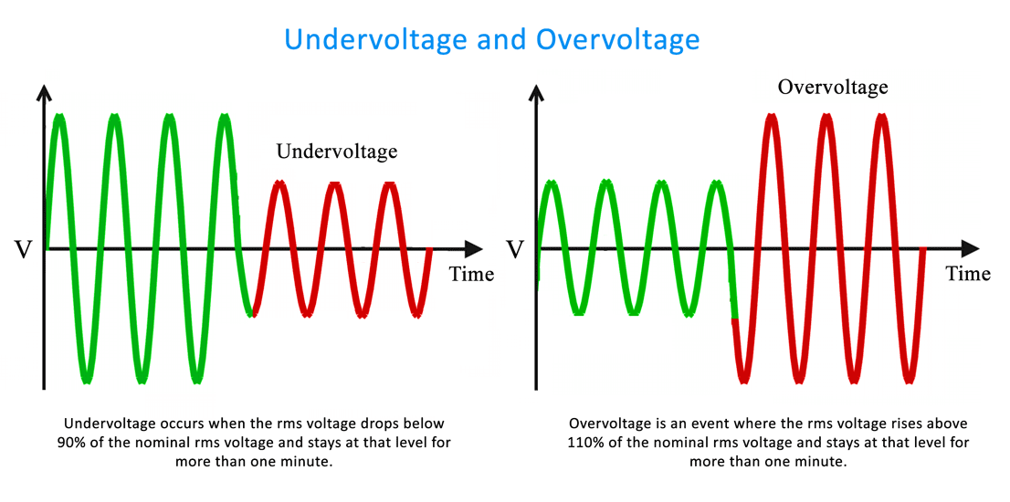
Undervoltage and overvoltage occur when voltage at the load drops below a minimum rated voltage or climbs above a maximum rated voltage for longer than a minute. Photo: TestGuy.
4. VAR imbalances from single-phase underground cable feeders
Underground cable feeders exhibit significantly higher capacitive effect than overhead lines. When a long single-phase or two-phase cable run is used, the capacitive charging current (VARs) is injected unevenly across the phases.
This VAR unbalance shifts the reactive power flow, raising voltage on the more capacitive phase while lowering it on others. Large single-phase underground laterals feeding subdivisions or commercial parks are especially prone to this effect, often requiring additional compensation to restore balance.
5. Single phasing of capacitor banks
Capacitor banks installed for voltage support can lose one phase when a fuse blows or a switch fails to close. The remaining two phases continue to supply VARs, but the missing phase creates an unequal reactive-power injection across the three phases.
The resulting VAR imbalance directly alters phase voltages and can amplify existing imbalances elsewhere on the circuit. Routine inspection and automatic detection of blown fuses are essential to prevent capacitor banks from becoming a source of chronic voltage imbalance.
6. Inherently unbalanced systems
Three-phase transformer banks assembled from single-phase units of unequal impedance or kVA ratings inherently deliver slightly different voltages on each phase. Open-delta configurations, commonly used for light loads, supply only two phases directly while deriving the third phase through the vector sum, introducing both magnitude and angle deviations.
These design-level imbalances are present under all loading conditions and cannot be corrected by load balancing alone. Proper bank matching or replacement with three-phase units eliminates this permanent source of imbalance.
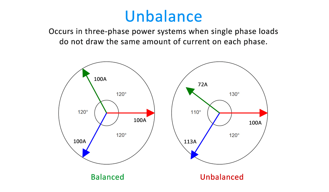
Unbalance occurs in three-phase power systems when single phase loads do not draw the same amount of current on each phase. Photo: Sonel.
7. Misconfigured or misoperating voltage regulators
Single-phase step-voltage regulators are often installed on each phase to control voltage independently. When regulators are set to different bandwidths, tap positions drift out of synchronization, or one phase regulator fails or is bypassed, unequal voltage corrections are applied.
The result is a deliberate but unintended voltage imbalance that compounds any existing load-related deviations. Coordinated control schemes and regular verification of regulator settings are required to keep the three phases balanced.
8. Phase angle shifts
Unequal line impedances produce different voltage drops in both magnitude and phase angle across the three phases. This may be caused by untransposed lines, single-phase laterals, or mismatched equipment. These angular shifts mean the 120° separation between phases is lost, even if magnitudes appear close.
The result drives negative-sequence currents that cause additional heating and torque pulsations in motors. Phase-angle imbalance is especially dangerous because standard voltmeters may not detect it; only sequence-component analysis reveals the full extent of the problem.
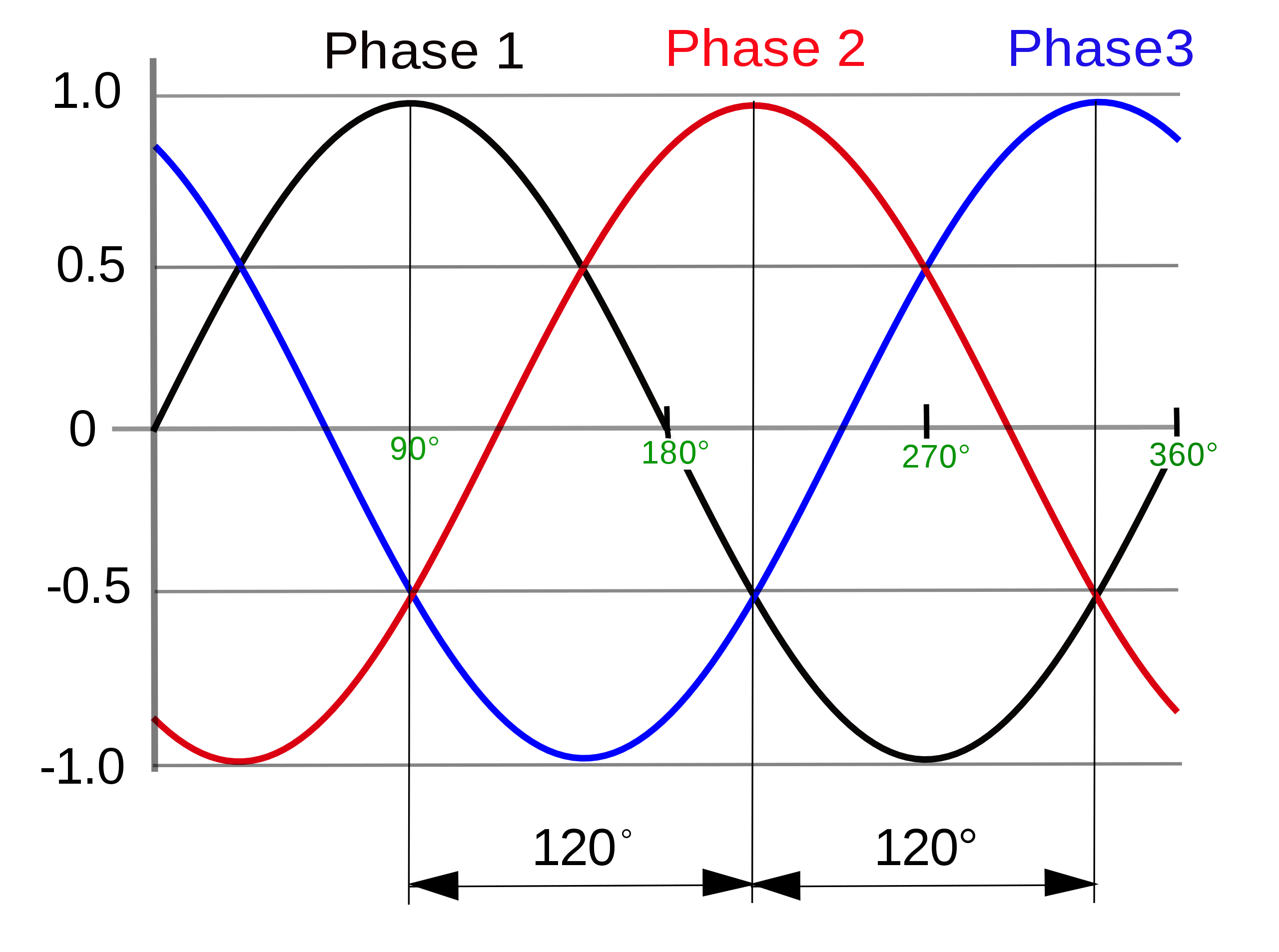
In an ideal 3-phase system, voltage and current waveforms are relatively in phase, free of distortion, and balanced between each other. Photo: Wikimedia.
Summary
Voltage imbalance stems from a wide range of sources spanning load distribution, generation, line design, reactive compensation, and equipment configuration. While some causes are inherent to the system topology, most can be minimized through deliberate phase balancing, regular maintenance, coordinated controls, and power quality monitoring.
Balanced phases distribute current and power evenly, minimizing I²R losses in conductors, transformers, and neutral wires. This leads to lower overall energy consumption and reduced heating in lines.
Three-phase motors, transformers, generators, and other rotating machinery experience far less overheating, torque pulsations, and mechanical stress. Fewer nuisance trips, overloads, or unexpected failures occur in motors, adjustable-speed drives, power electronics, and sensitive loads.
These improvements translate to lower electricity bills, reduced costs on equipment replacement, improved power factor, and greater system reliability.